
Vehicle-mounted storage box

a storage box and vehicle-mounted technology, applied in the field of auto parts, can solve the problems of inability to meet the loading capacity requirement of vehicle-mounted storage boxes, inconvenient storage, and high labor intensity of drawers, and achieve the effect of high loading capacity

Inactive Publication Date: 2017-11-30
ZHANG MINGHUA +1
View PDF4 Cites 5 Cited by
  • Summary
  • Abstract
  • Description
  • Claims
  • Application Information

AI Technical Summary

Benefits of technology

This invention provides a vehicle-mounted storage box that has push-pull drawers and a high loading capacity. Compared to existing storage boxes, it saves time and labor for users and can carry heavy objects. The sliding mechanisms ensure smooth sliding and prevent excessive clearance and impurities. The guide track is designed to withstand heavy loads and has resistance to dust, sand, water, and weather. The drawer can slide freely and remains unobstructed with high efficiency.

Problems solved by technology

However, when they need to take out the articles in the storage boxes, they have to move away the top cover of the storage boxes as well as all the articles stacked on the top.
It always consumes a lot of time and labor to do this, because the top cover is big and the articles stacked on the top are many.
However, the design sliding mechanism of existing drawers is so defectively designed that the drawers cannot bear relatively high load and thus cannot meet the requirement on loading capacity of vehicle-mounted storage boxes.

Method used


Image

  • Vehicle-mounted storage box
  • Vehicle-mounted storage box
  • Vehicle-mounted storage box

Examples


Embodiment Construction

[0026]The invention is hereinafter described in detail with reference to an embodiment and the drawings, to better illustrate the technical problem the invention is designed to solve, as well as the technical solution and beneficial effects. It should be understood that the embodiment described hereinafter is illustrative and non-restrictive in every respect.

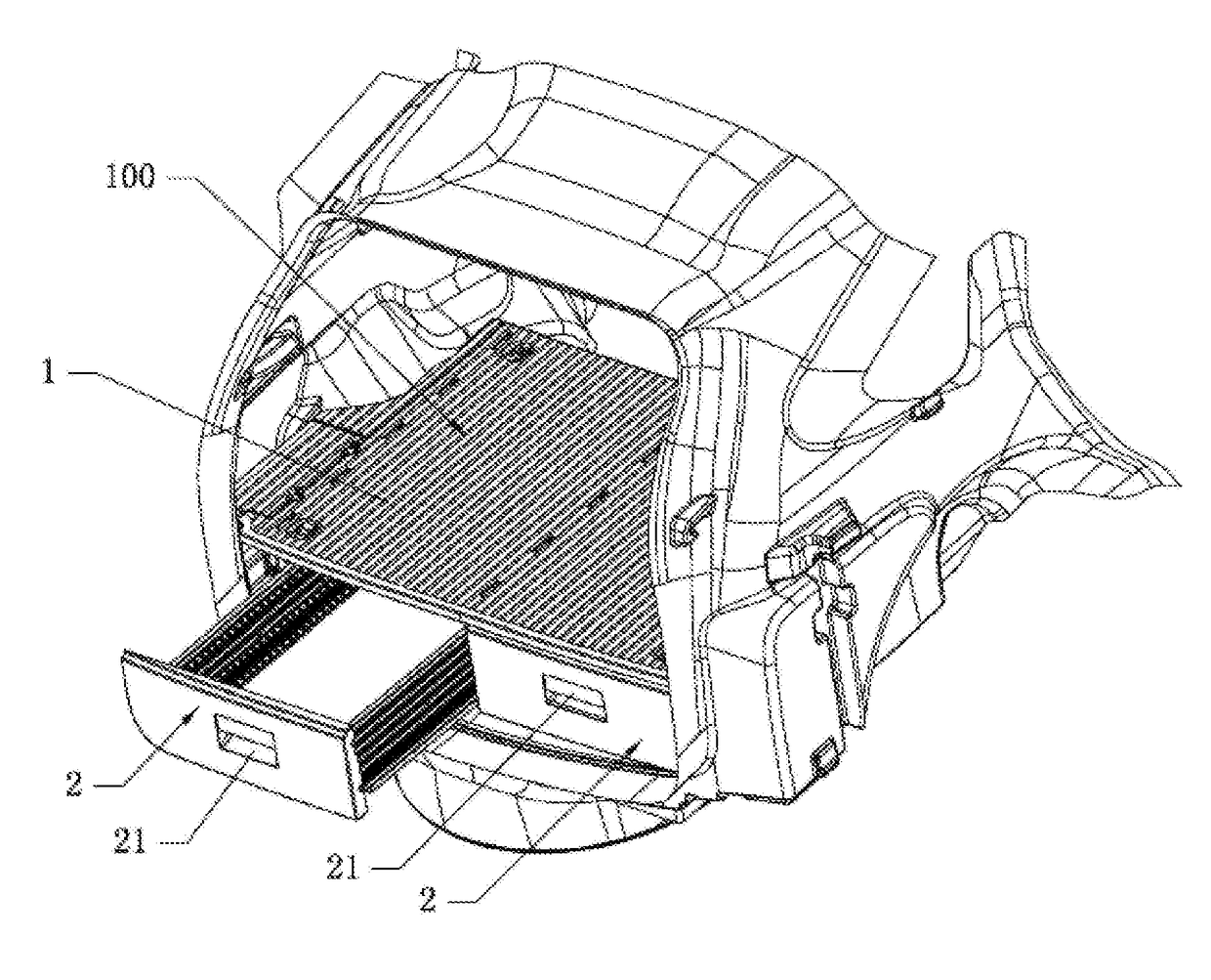
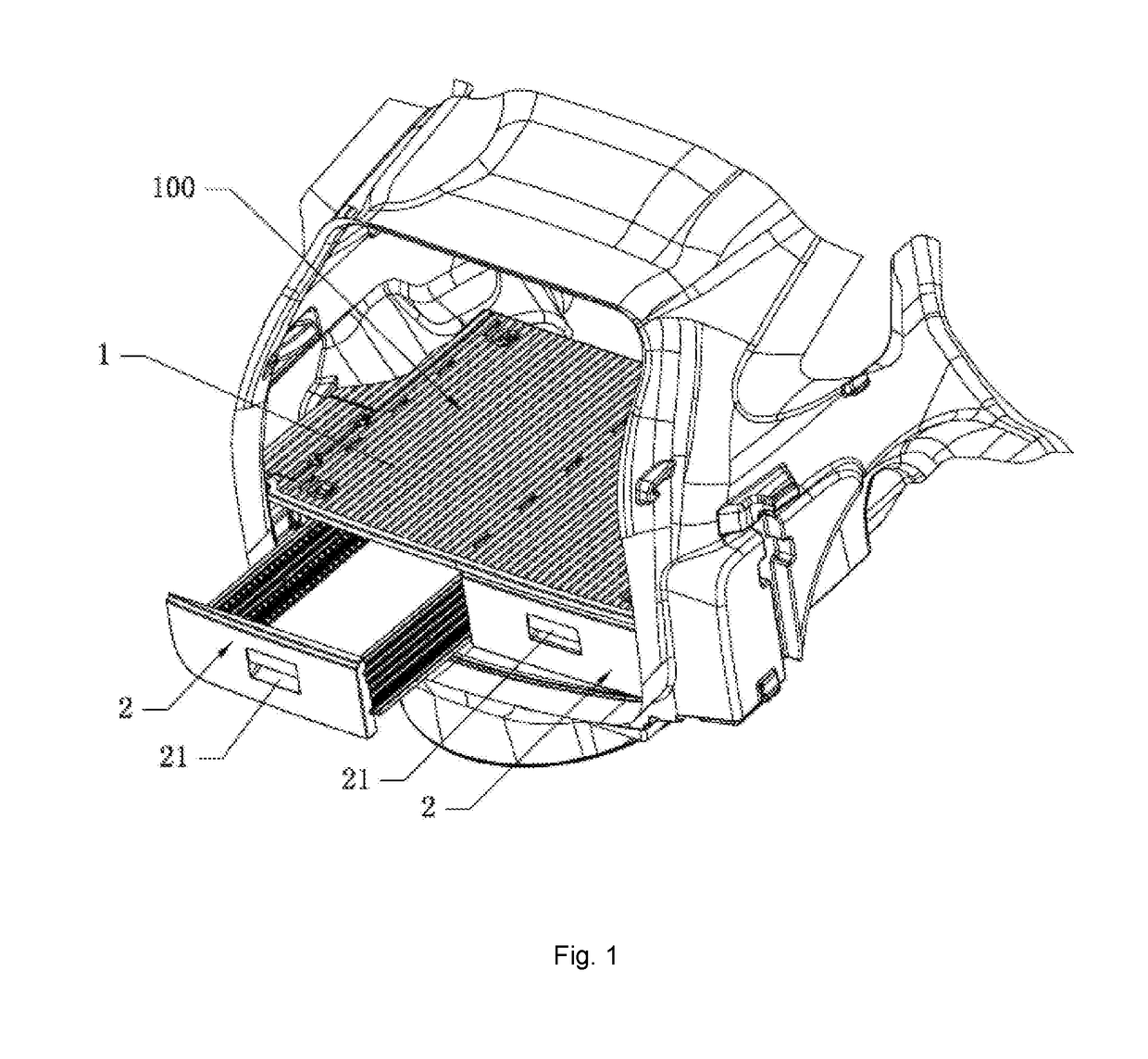
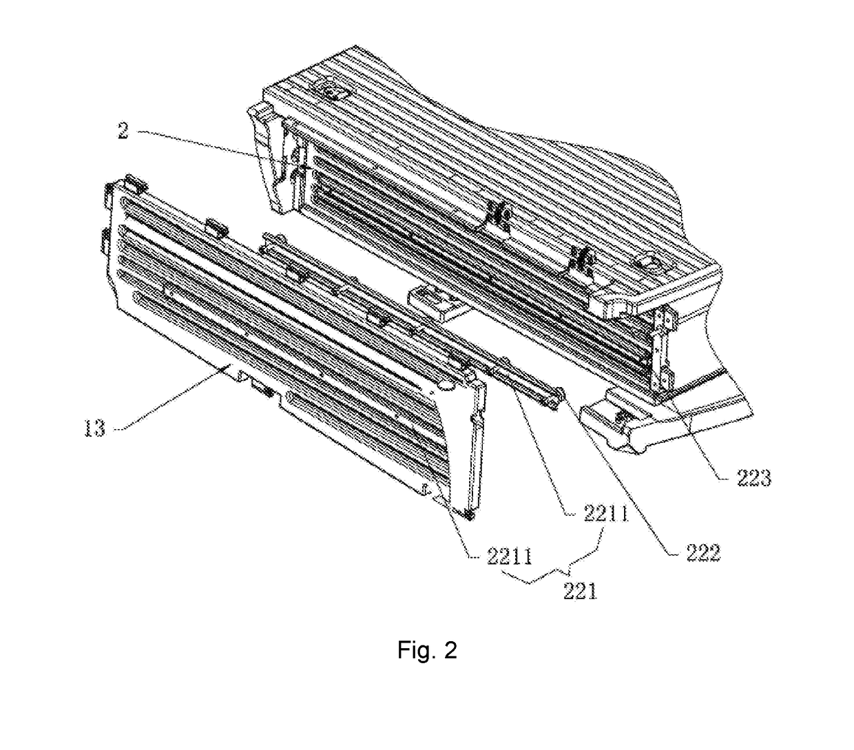
[0027]An embodiment of the invention is shown in FIG. 1-FIG. 9. A vehicle-mounted storage box 100 comprises boxes 1; the boxes 1 are provided with push-pull drawers 2; both sides of the drawer 2 are provided with a sliding mechanism 22 that is used to slide the drawer 2; the mechanism 22 comprises guide pulley seats 221, guide pulleys 222, and a guide track 223; the guide pulleys 222 are installed on the guide pulley seats 221, and are rotatable; the guide track 223 is located at one side of the drawer 2; the guide pulley seats 221 are fixed in the box 1 at the positions corresponding to the location of the guide track 223; the ...


PUM


Abstract

This utility model relates to a vehicle-mounted storage box, which could be a new product in the field of auto parts. The vehicle-mounted storage box includes boxes, which are provided with push-pull drawers. Both sides of the drawer are provided with a sliding mechanism that is used to slide the drawer. The mechanism comprises guide pulley seats, guide pulleys, and a guide track. The guide pulleys are installed on the guide pulley seats and are rotatable. The guide track is located at one side of the drawer. The guide pulley seats are fixed in the box at the positions corresponding to the location of the guide track. The guide pulleys are embedded in the guide track and can roll on the guide track. There is a ringed groove carved at the outer edge of the guide pulley, and there are raised lines on the guide track, which can be set in the ringed groove. The shape of the ringed groove is well matched with that of the raised line. The storage box is provided with push-pull drawers, so that users can use the storage box directly without having to remove the articles on it and lift its top covers, and thus save a lot of time and labor. Meanwhile, the raised line structure at the contact area between the guide track and guide pulleys in the sliding mechanisms on both sides of the drawer enables the drawer to carry relatively heavy objects.

Description

FIELD OF THE INVENTION[0001]This invention relates to the field of auto parts, and particularly relates to a vehicle-mounted storage box.BACKGROUND OF THE INVENTION[0002]Vehicle-mounted storage boxes are installed in the trunk of cars and used for storing articles. People are used to stack articles on the top of the storage boxes to fully use the limited room. However, when they need to take out the articles in the storage boxes, they have to move away the top cover of the storage boxes as well as all the articles stacked on the top. It always consumes a lot of time and labor to do this, because the top cover is big and the articles stacked on the top are many. Therefore, it is necessary to design drawers in vehicle-mounted storage boxes. However, the design sliding mechanism of existing drawers is so defectively designed that the drawers cannot bear relatively high load and thus cannot meet the requirement on loading capacity of vehicle-mounted storage boxes.[0003]Reference to any ...

Claims


Application Information

Patent Timeline
IPC IPC(8): B60R5/04B60R11/00
CPCB60R2011/0094B60R5/044B60R5/04B60R7/02
Inventor WANG, DEMING
Owner ZHANG MINGHUA
Learn More