Permanent Magnet Electric Machine

a permanent magnet, electric machine technology, applied in the direction of motor starters, magnetic circuit rotating parts, magnetic circuit shape/form/construction, etc., can solve problems such as motor degradation

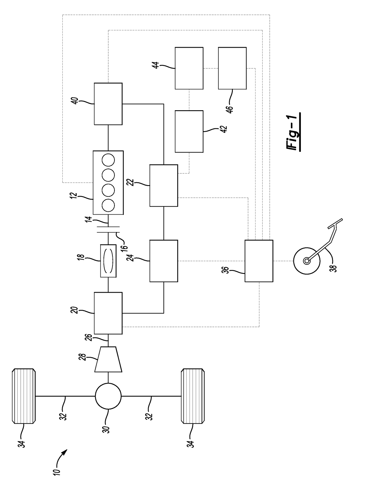
Active Publication Date: 2017-11-23
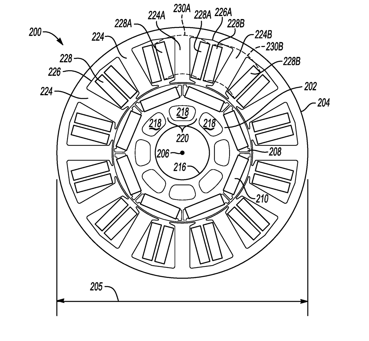
GM GLOBAL TECH OPERATIONS LLC
View PDF18 Cites 18 Cited by
  • Summary
  • Abstract
  • Description
  • Claims
  • Application Information

AI Technical Summary

Benefits of technology

[0003]An interior permanent magnet electric machine includes a stator having a plurality of teeth disposed around a circumference oriented radially towards a center defining slots interposed between each of the teeth, and a conductive winding wrapped around each of the teeth of the stator to receive an electrical current. The electric machine also includes a rotor which is rotatable relat

Problems solved by technology

The physical contacts may wear over

Method used


Image

  • Permanent Magnet Electric Machine
  • Permanent Magnet Electric Machine
  • Permanent Magnet Electric Machine

Examples


Embodiment Construction

[0011]Embodiments of the present disclosure are described herein. It is to be understood, however, that the disclosed embodiments are merely examples and other embodiments can take various and alternative forms. The figures are not necessarily to scale; some features could be exaggerated or minimized to show details of particular components. Therefore, specific structural and functional details disclosed herein are not to be interpreted as limiting, but merely as a representative basis for teaching one skilled in the art to variously employ the present invention. As those of ordinary skill in the art will understand, various features illustrated and described with reference to any one of the figures can be combined with features illustrated in one or more other figures to produce embodiments that are not explicitly illustrated or described. The combinations of features illustrated provide representative embodiments for typical applications. Various combinations and modifications of ...


PUM


Abstract

An interior permanent magnet electric machine includes a stator having a plurality of teeth disposed around a circumference oriented radially towards a center defining slots interposed between each of the teeth, and a conductive winding wrapped around each of the teeth of the stator to receive an electrical current. The electric machine also includes a rotor which is rotatable relative to the stator. The rotor defines a plurality of openings to receive permanent magnets near an outer portion of the rotor and a number of spokes interposed between mass reduction cutouts located closer to the center relative to the permanent magnets. Each of the permanent magnets defines a magnetic pole and each of the spokes is circumferentially aligned with one of the magnetic poles.

Description

TECHNICAL FIELD[0001]The present disclosure related to hybrid vehicle propulsion system electric machine.INTRODUCTION[0002]Combustion engines may have an electric starter coupled to the engine to turn a crankshaft leading up to a start event. The electric starter can be an electric motor having contact brushes to conduct current between stationary wires on a stator portion and moving parts of a rotor portion. The physical contacts may wear over time leading to motor degradation. Additionally, a brushed motor delivers substantially zero torque near the upper bound of its available speed range.SUMMARY[0003]An interior permanent magnet electric machine includes a stator having a plurality of teeth disposed around a circumference oriented radially towards a center defining slots interposed between each of the teeth, and a conductive winding wrapped around each of the teeth of the stator to receive an electrical current. The electric machine also includes a rotor which is rotatable relat...

Claims


Application Information

Patent Timeline
IPC IPC(8): B60L11/18H02K1/14F02N11/08H02K1/27
CPCB60L11/18H02K1/146B60L2220/50F02N11/0851H02K1/276B60K2006/268F02N11/006F02N11/0862F02N2200/022F02N2300/102H02K7/006H02K21/16B60K6/20B60W20/00
Inventor HAO, LEINAMUDURI, CHANDRA S.PANDI, MURALINEHL, THOMAS W.
Owner GM GLOBAL TECH OPERATIONS LLC
Why Eureka
Try Eureka