
Method, apparatus, and system for controlling a timber-working device

a technology of timber-working devices and control devices, applied in the direction of agriculture, manufacturing tools,auxillary saw devices, etc., can solve the problems of chainsaws, timber-working devices including hazards

Active Publication Date: 2017-11-02
WARATAH NZ
View PDF12 Cites 0 Cited by
  • Summary
  • Abstract
  • Description
  • Claims
  • Application Information

AI Technical Summary

Problems solved by technology

A significant hazard associated with timber-working devices including a chainsaw is a phenomenon known as “chain shot”.

Method used


Image

  • Method, apparatus, and system for controlling a timber-working device
  • Method, apparatus, and system for controlling a timber-working device
  • Method, apparatus, and system for controlling a timber-working device

Examples


Embodiment Construction

[0024]Throughout this specification, the word “comprise”, or variations thereof such as “comprises” or “comprising”, will be understood to imply the inclusion of a stated element, integer or step, or group of elements integers or steps, but not the exclusion of any other element, integer or step, or group of elements, integers or steps.

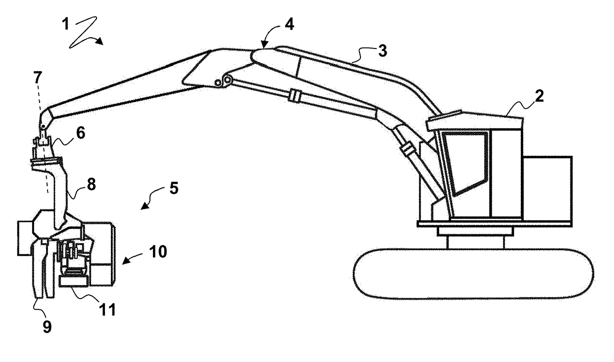
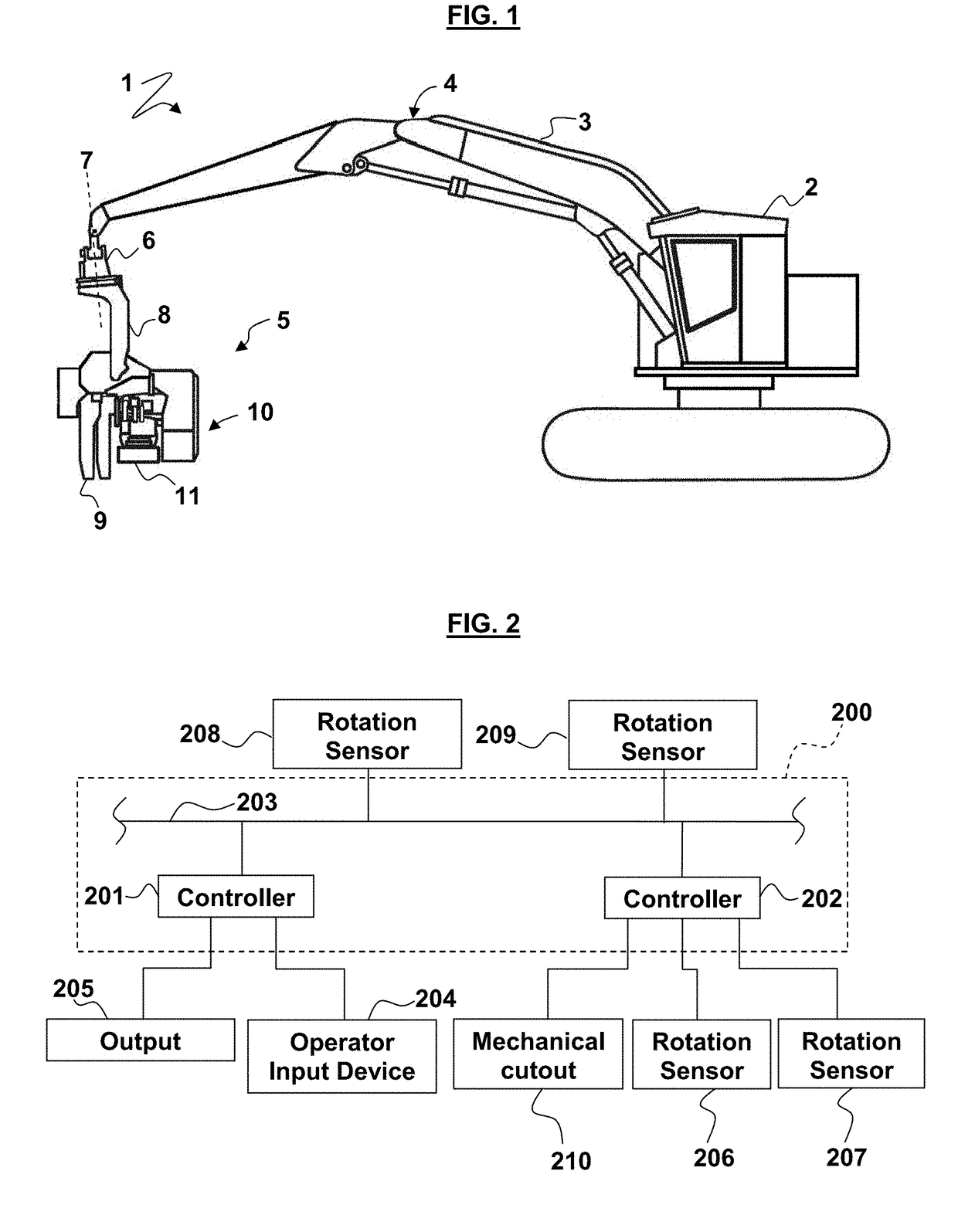
[0025]FIG. 1 illustrates a timber-working system including a carrier 1 for use in forest harvesting. The carrier 1 includes an operator cab 2 from which an operator (not shown) controls the carrier 1. The carrier 1 further includes an articulated arm 3, which has an articulated joint 4, as well as a further pivot point at the point of connection (not shown) to the carrier 1. A timber-working device in the form of a harvester head 5 is connected to the arm 3 of the carrier 1. Connection of the harvester head 5 to the arm 3 includes a rotator 6, configured to rotate the harvester head about the generally vertical axis of rotation marked by dashed line 7...


PUM


Abstract

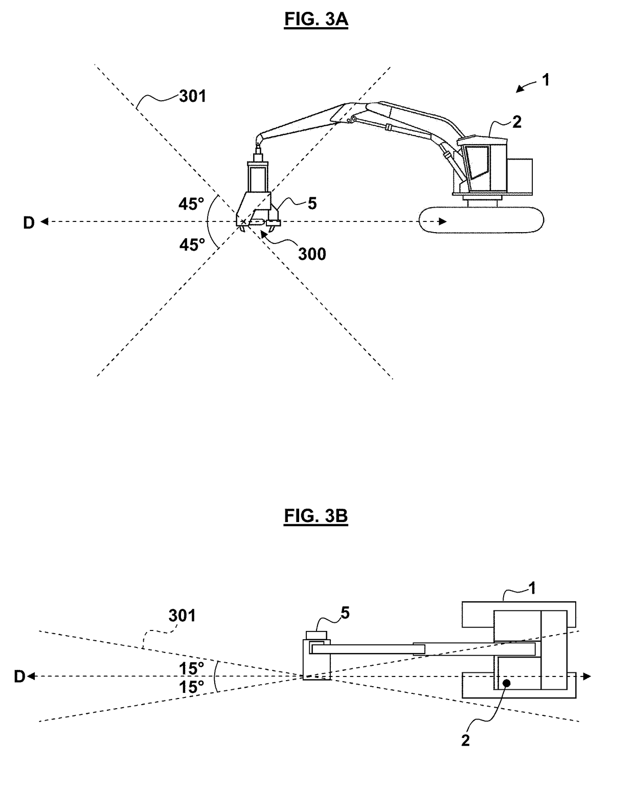
Method, apparatus, and system for operation of a timber-working device configured to perform at least one operation having an associated hazard zone. At least one signal from at least one orientation sensor associated with the timber-working head may indicate whether a predetermined location is within the hazard zone based on the orientation of the timber-working head. Operation of the timber-working head can be controlled based on the signal.

Description

[0001]This application is a continuation of U.S. patent application Ser. No. 14 / 049,882, filed on 9 Oct. 2013, which claimed the benefit of New Zealand Patent Application Number 602931 filed Oct. 10, 2012, the entire contents of which are incorporated herein by reference.FIELD OF THE DISCLOSURE[0002]The present disclosure relates to a method, apparatus, and system for controlling a timber-working device.BACKGROUND OF THE DISCLOSURE[0003]It is well-known to mount timber-working devices to a carrier vehicle in order to perform a number of operations in connection with timber processing. These operations may include one, or a combination of, grappling and felling a standing tree, delimbing a felled stem, debarking the stem, and cutting the stem into logs—commonly using at least one chainsaw.[0004]A significant hazard associated with timber-working devices including a chainsaw is a phenomenon known as “chain shot”. Chain shot results from the saw chain breaking, following which parts fr...

Claims


Application Information

Patent Timeline
Patent Type & Authority Applications(United States)
IPC IPC(8): A01G23/02A01G23/08B27G19/00B27G21/00
CPCB27G21/00A01G23/08B27G19/00A01G23/02
Inventor KAYE, BRETT JAMESMARRIAGE, CLINTON CHARLESJAMES, MICHAEL FRANCISLAWLER, RICHARD JOHN
Owner WARATAH NZ
Learn More