
Collimating light emitted by a fiber via an array of lenslets on a curved surface

a technology of collimating optical system and fiber, which is applied in the direction of scanning light guides, instruments, optics, etc., can solve the problems of complicating the design of collimating optical system and challenging the ability to achieve the desired scanning optical probe beam properties

Active Publication Date: 2017-08-31
QUALCOMM INC
View PDF0 Cites 11 Cited by
  • Summary
  • Abstract
  • Description
  • Claims
  • Application Information

AI Technical Summary

Benefits of technology

The patent describes an optical element arrangement that includes a first optical element. The first optical element emits light beams at different positions and has a curved surface with lenslets that receive and collimate the light beams. The collimated light beams have a specific field angle relative to the system axis. The technical effect of this arrangement is that it allows for precise collimation of light beams, which can improve the performance and accuracy of optical systems.

Problems solved by technology

Achieving desired scanning optical probe beam properties is challenging for various reasons.
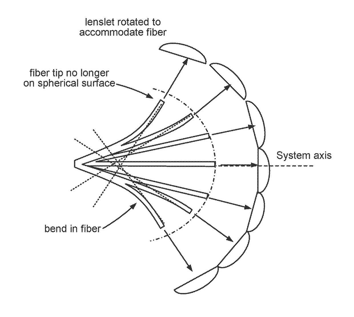
This fiber tip path is approximately spherical for small angular motion, but becomes elliptical for larger angular motions as the fiber 110 begins to bend, which complicates the design of a collimating optical system.

Method used


Image

  • Collimating light emitted by a fiber via an array of lenslets on a curved surface
  • Collimating light emitted by a fiber via an array of lenslets on a curved surface
  • Collimating light emitted by a fiber via an array of lenslets on a curved surface

Examples


Embodiment Construction

[0025]Aspects of the disclosure are disclosed in the following description and related drawings directed to specific embodiments of the disclosure. Alternate embodiments may be devised without departing from the scope of the disclosure. Additionally, well-known elements of the disclosure will not be described in detail or will be omitted so as not to obscure the relevant details of the disclosure.

[0026]The words “exemplary” and / or “example” are used herein to mean “serving as an example, instance, or illustration.” Any embodiment described herein as “exemplary” and / or “example” is not necessarily to be construed as preferred or advantageous over other embodiments. Likewise, the term “embodiments of the disclosure” does not require that all embodiments of the disclosure include the discussed feature, advantage or mode of operation.

[0027]Embodiments relate to an optical element in a fiber-based lidar system that collimates light over large field angles in a manner that is angle indepe...


PUM


Abstract

An embodiment is directed to an optical element arrangement including at least one optical element. A first optical element includes a fiber and a curved surface. The fiber emits light beams during oscillation at different angular positions relative to a system axis of the first optical element. The curved surface includes an array of lenslets. Each of the lenslets in the array of lenslets is configured to receive light beams from the fiber that are emitted within a particular range of the first curved surface and to collimate the light beams received by the lenslet at a lenslet-specific field angle relative to the system axis. In other embodiments, one or more additional optical elements with respective fibers can be deployed as part of the optical element arrangement, and any of the optical elements in the optical element arrangement may include multiple curved surfaces with respective lenslet arrays.

Description

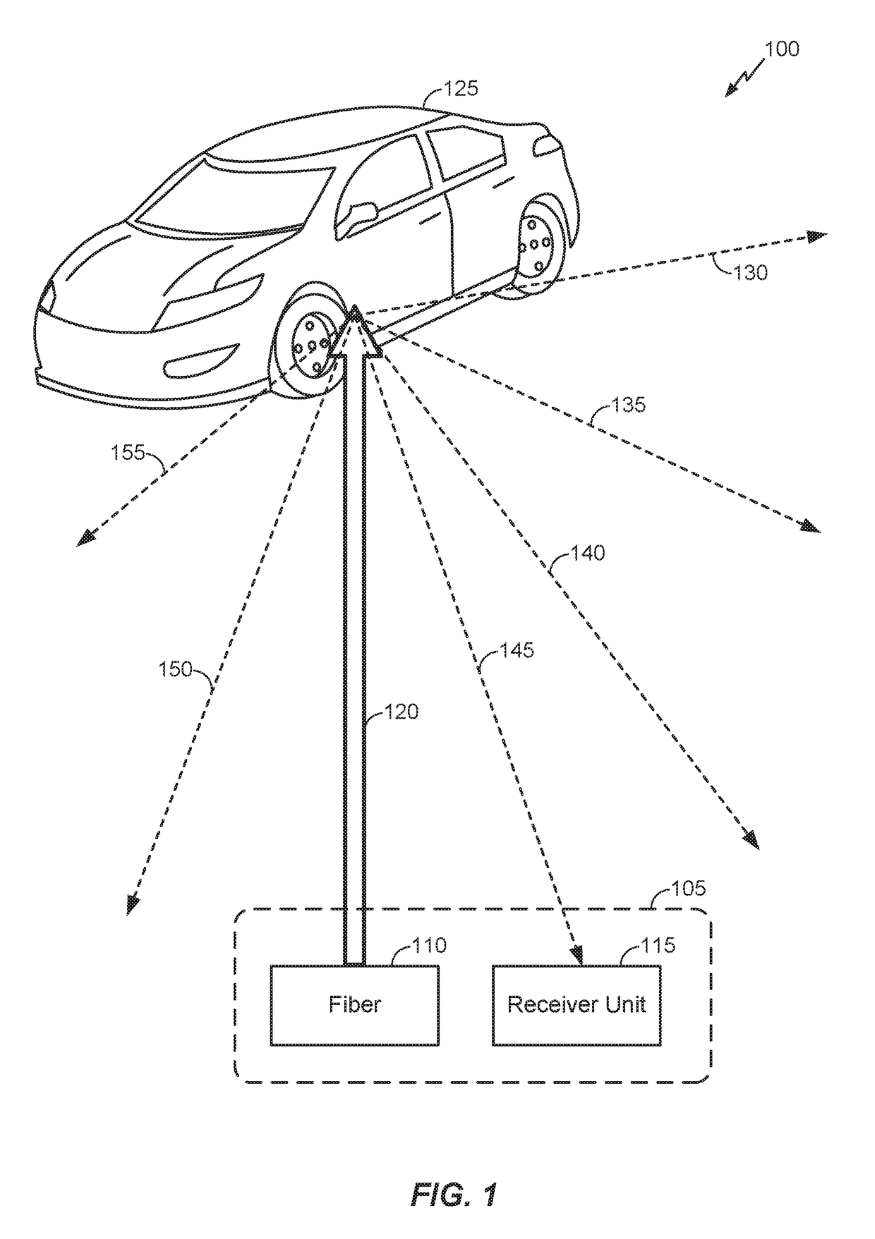
CROSS-REFERENCE TO RELATED APPLICATIONS[0001]The present application for patent claims the benefit of U.S. Provisional Application No. 62 / 300,690, entitled “FIBER BASED LIDAR AND COLLIMATING OPTICS SYSTEM”, filed Feb. 26, 2016, which is by the same inventors as the subject application, assigned to the assignee hereof and hereby expressly incorporated by reference herein in its entirety.BACKGROUND[0002]1. Field of the Disclosure[0003]Embodiments relate to collimating light emitted by a fiber via an array of lenslets on a curved surface.[0004]2. Description of the Related Art[0005]Some object detection systems (e.g., collimating optical systems such as the Hyperion lidar project) rely upon the emission of a scanning optical probe beam by a scanning device. When this probe beam strikes an object within a threshold distance (e.g., 100 m) from the fiber that emits the scanning optical probe beam away), light is scattered from the object back to a receiver unit at the scanning device that...

Claims


Application Information

Patent Timeline
Patent Type & Authority Applications(United States)
IPC IPC(8): G02B26/10G01S7/481G02B3/00
CPCG02B26/103G02B3/0037G02B2006/0098G01S7/4818G01S7/4817
Inventor GRUHLKE, RUSSELL
Owner QUALCOMM INC
Learn More