
Intervertebral disc implant and method for restoring function to a damaged functional spinal unit

a technology of intervertebral discs and functional spines, which is applied in the field of intervertebral disc implants and methods for restoring function to a damaged functional spine, can solve the problems of implant migration into the vertebral body, implant displacement, and similar risk of adjacent segment degeneration, so as to avoid the risk of implant loosening

Active Publication Date: 2017-07-20
MUHLBAUER MANFRED
View PDF2 Cites 2 Cited by
  • Summary
  • Abstract
  • Description
  • Claims
  • Application Information

AI Technical Summary

Benefits of technology

The invention provides better implants for replacing cervical discs that have two separate parts for flexion and extension, as well as side-bending and rotation. The flexion/extension part can be adjusted widely, and the range of motion for side-bending and rotation is not restricted after implantation. The implants have a curved shape that matches the natural movement of the spine, which helps to distribute forces over a wider area and avoid point-like contact between the two surfaces. The edge design of the implants allows for unrestricted motion within the natural range of motion of the spine, reducing the risk of loosening and replicating natural conditions. The outer edges of the implants do not interfere with the movement of the spine.

Problems solved by technology

The technical problem addressed in this patent is the design of a cervical disc prosthesis that can replicate the natural motion of the spine and allow motion through two independent centers of rotation (CORs) while also allowing for inter-individual differences and degenerative changes in the spine. Most currently available cervical disc prosthesis designs have limitations in replicating the natural motion of the spine and can cause pain and degeneration of adjacent segments. The patent aims to address these issues by designing a cervical disc prosthesis that can better replicate the biomechanics of the spine and allow for natural motion.

Method used


Image

  • Intervertebral disc implant and method for restoring function to a damaged functional spinal unit
  • Intervertebral disc implant and method for restoring function to a damaged functional spinal unit
  • Intervertebral disc implant and method for restoring function to a damaged functional spinal unit

Examples


Embodiment Construction

[0039]Implant devices and methods disclosed herein provide improved two part intervertebral / cervical disc prostheses for total cervical disc replacement which have two separate independent centers of rotation or “CORs” for flexion / extension and side-bending / rotation and the COR for flexion / extension is operable to be widely variable and further, the range of motion for side-bending and coupled rotation is hardly restricted by the flexion / extension angle after implantation.

[0040]As disclosed herein the two parts, partners, or members of one or more aspects of the invention may form a coupling, joint, or pair of articulating, sliding or bearing surfaces operable to replace a damaged intervertebral disc and / or posterior elements of a functional spinal unit.

[0041]One or more embodiments of the intervertebral disc implant described herein provides for dorsoventral motion (flexion / extension) and laterolateral motion (side-bending) and rotation independently from each other over independen...


PUM


Abstract

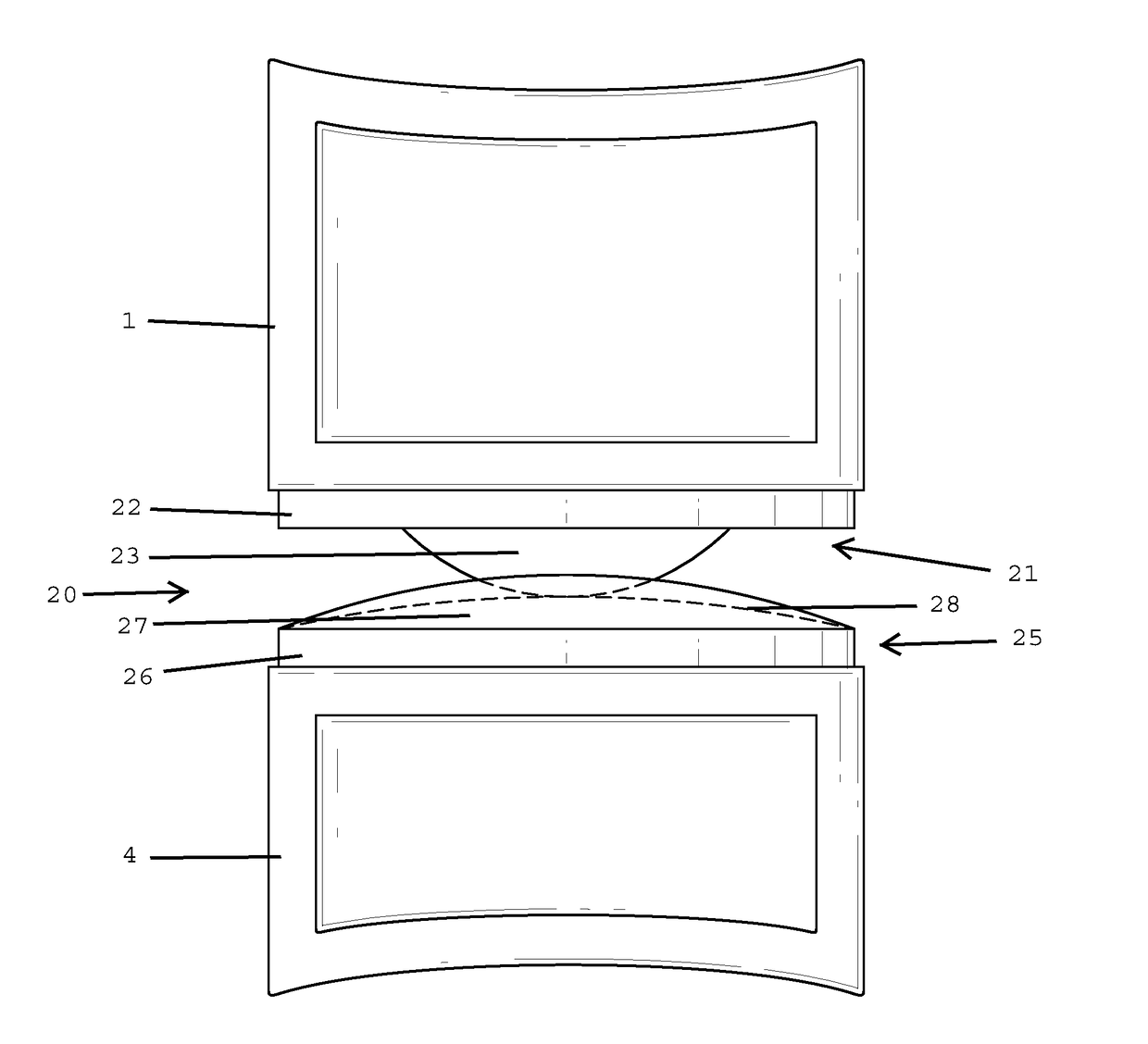
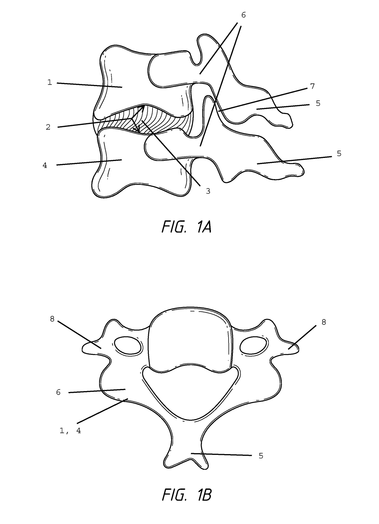
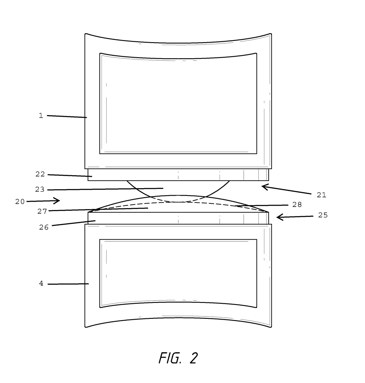
Presented are intervertebral disc implants (20) for the total replacement of an intervertebral disc (3) within the cervical spine, comprising two articulating members (21, 25), where the inferior member (21) on its upper surface is adapted for engaging an upper vertebral body (1) and its lower surface has an convex projection (23), and the inferior member (25) on its lower surface is adapted for engaging a lower vertebral body (4) and its upper surface has an saddle shaped projection (27), which is convex in its longitudinal anterior-posterior profile and which is concave in its transversal lateral profile with the general same diameter as the convex projection (23) of the superior member (21), therefore allowing flexion-extension-motion over a variable center of rotation, and in addition allowing rotation and lateral bending through a second independent center of rotation which is located above the intervertebral disc implant (20) at a distance which is defined by the diameter of the convex projection (23) of the superior member (21), therefore allowing coupled motion for rotation and lateral bending independently from flexion/extension, and therefore more closely replicating the natural kinematics of a cervical disc.

Description


Claims


Application Information

Patent Timeline
Owner MUHLBAUER MANFRED
Learn More