
Tip shrouded turbine rotor blades

a technology for turbine rotor blades and accessories, which is applied in the direction of machines/engines, sustainable transportation, climate sustainability, etc., can solve the problems of troublesome shrouds and difficult to take full advantage of the benefits

Inactive Publication Date: 2017-06-29
GENERAL ELECTRIC CO
View PDF4 Cites 16 Cited by
  • Summary
  • Abstract
  • Description
  • Claims
  • Application Information

AI Technical Summary

Benefits of technology

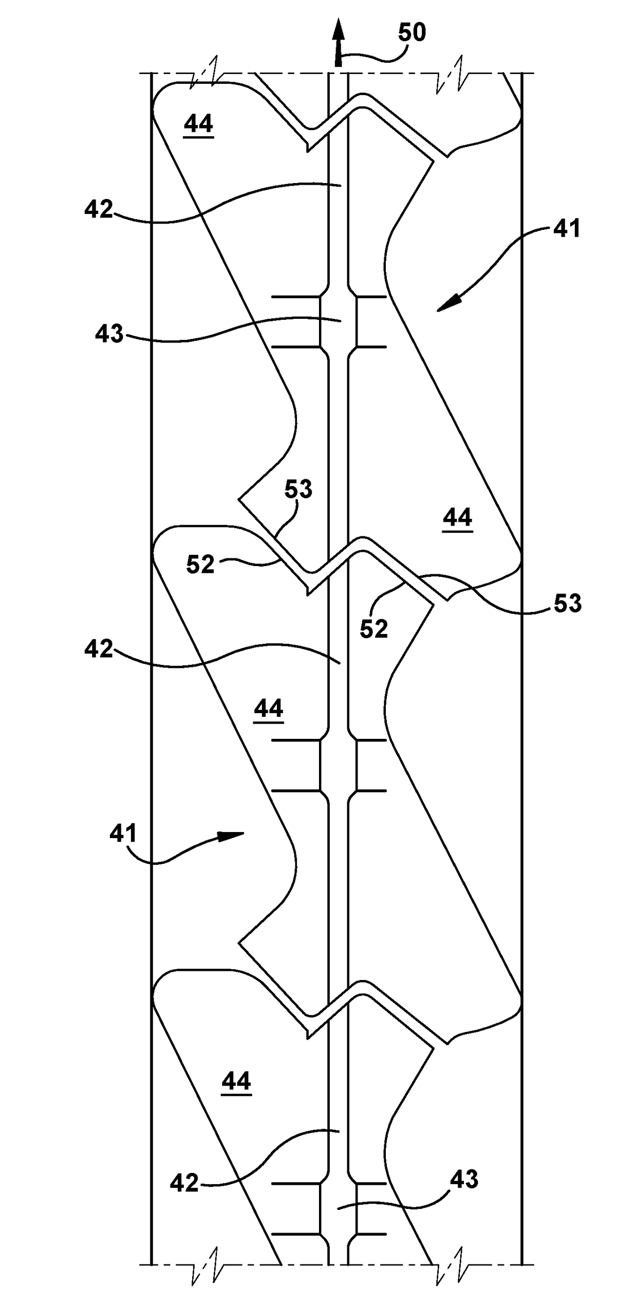
The patent describes a rotor blade for a gas turbine with a cavitied tip shroud. The tip shroud has a seal rail with a hollow cavity that includes a mouth. The tip shroud is divided into three reference zones, and the seal rail has a cavity in one of these zones. The technical effect of the design is to improve the efficiency and performance of gas turbines by providing improved airflow and reduced air leakage.

Problems solved by technology

However, taking full advantage of the benefits is difficult considering the weight that the tip shroud adds to the assembly and the other design criteria, which include enduring thousands of hours of operation exposed to high temperatures and extreme mechanical loads.
Thus, while large tip shrouds are desirable because of the effective manner in which they seal the gas path and the stable connections or interfaces they form between neighboring rotor blades, it will be appreciated that such shrouds are troublesome because of the increased pull loads on the rotor blade, particularly at the base of the airfoil because it must support the entire load of blade.

Method used


Image

  • Tip shrouded turbine rotor blades
  • Tip shrouded turbine rotor blades
  • Tip shrouded turbine rotor blades

Examples


Embodiment Construction

[0023]Aspects and advantages of the present application are set forth below in the following description, or may be obvious from the description, or may be learned through practice of the invention. Reference will now be made in detail to present embodiments of the invention, one or more examples of which are illustrated in the accompanying drawings. The detailed description uses numerical designations to refer to features in the drawings. Like or similar designations in the drawings and description may be used to refer to like or similar parts of embodiments of the invention. As will be appreciated, each example is provided by way of explanation of the invention, not limitation of the invention. In fact, it will be apparent to those skilled in the art that modifications and variations can be made in the present invention without departing from the scope or spirit thereof. For instance, features illustrated or described as part of one embodiment may be used on another embodiment to ...


PUM


Abstract

A rotor blade for a gas turbine that includes an airfoil and a tip shroud. The tip shroud may have a seal rail that projects radially from an outboard surface and extends circumferentially. The tip shroud may further include: a rotationally leading circumferential face; a rotationally trailing circumferential face; and an outboard face of the seal rail. The tip shroud may be circumferentially divided into three parallel reference zones: a rotationally leading edge zone, a rotationally trailing edge zone and, formed between and separating those, a middle zone. The seal rail may include a hollow cavity wholly contained within at least one of the rotationally leading edge zone and the rotationally trailing edge zone. The cavity may include a mouth formed through at least one of the rotationally leading circumferential face, the rotationally trailing circumferential face, and the outboard face of the seal rail.

Description

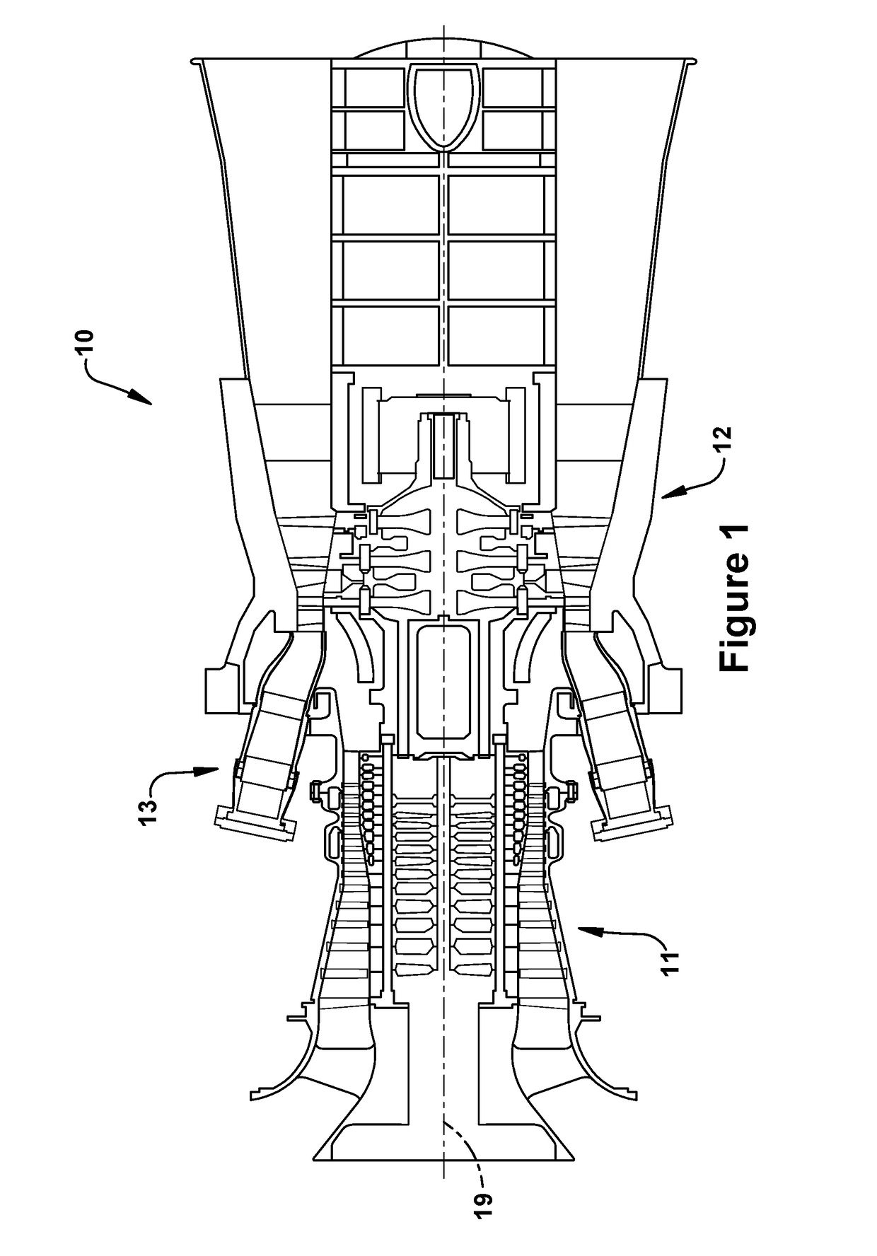
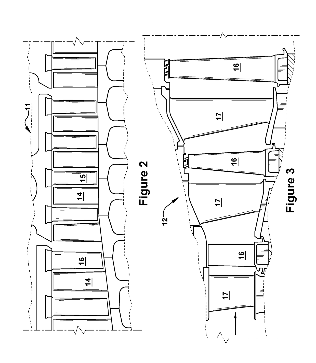
BACKGROUND OF THE INVENTION[0001]The present application relates generally to apparatus, methods and / or systems concerning the design, manufacture, and use of rotor blades in combustion or gas turbine engines. More specifically, but not by way of limitation, the present application relates to apparatus and assemblies pertaining to turbine rotor blades having tip shrouds.[0002]In combustion or gas turbine engines (hereinafter “gas turbines”), it is well known that air pressurized in a compressor is used to combust fuel in a combustor to generate a flow of hot combustion gases, whereupon the gases flow downstream through one or more turbines so that energy can be extracted therefrom. In accordance with such engines, generally, rows of circumferentially spaced rotor blades extend radially outwardly from a supporting rotor disc. Each rotor blade typically includes a dovetail that permits assembly and disassembly of the blade in a corresponding dovetail slot in the rotor disc, as well as...

Claims


Application Information

Patent Timeline
IPC IPC(8): F01D5/22F01D11/00
CPCF01D5/225F01D11/006F05D2240/307F05D2230/10F05D2220/32F01D5/18F01D5/181Y02T50/60F01D5/141F01D5/147F05D2240/24
Inventor MCDUFFORD, MICHAELJONES, JEFFREY CLARENCE
Owner GENERAL ELECTRIC CO
Learn More