
Bicycle pump

a technology of bicycles and pumps, applied in the direction of pump components, positive displacement liquid engines, liquid fuel engine components, etc., can solve the problems of low comfort of use, unsatisfactory effect of pumping operation, unwieldy kind of use, etc., and achieve the effect of improving the state of the ar

Active Publication Date: 2017-06-15
CRANK BROS INC
View PDF41 Cites 12 Cited by
  • Summary
  • Abstract
  • Description
  • Claims
  • Application Information

AI Technical Summary

Benefits of technology

The patent text describes various improvements to bicycle pumps, including making them more comfortable to use, storing them when not in use, and preventing the handle assembly from opening accidentally. The technical effects of these improvements are to make the pump more user-friendly and to improve its overall quality and performance.

Problems solved by technology

This results in a low comfort of use.
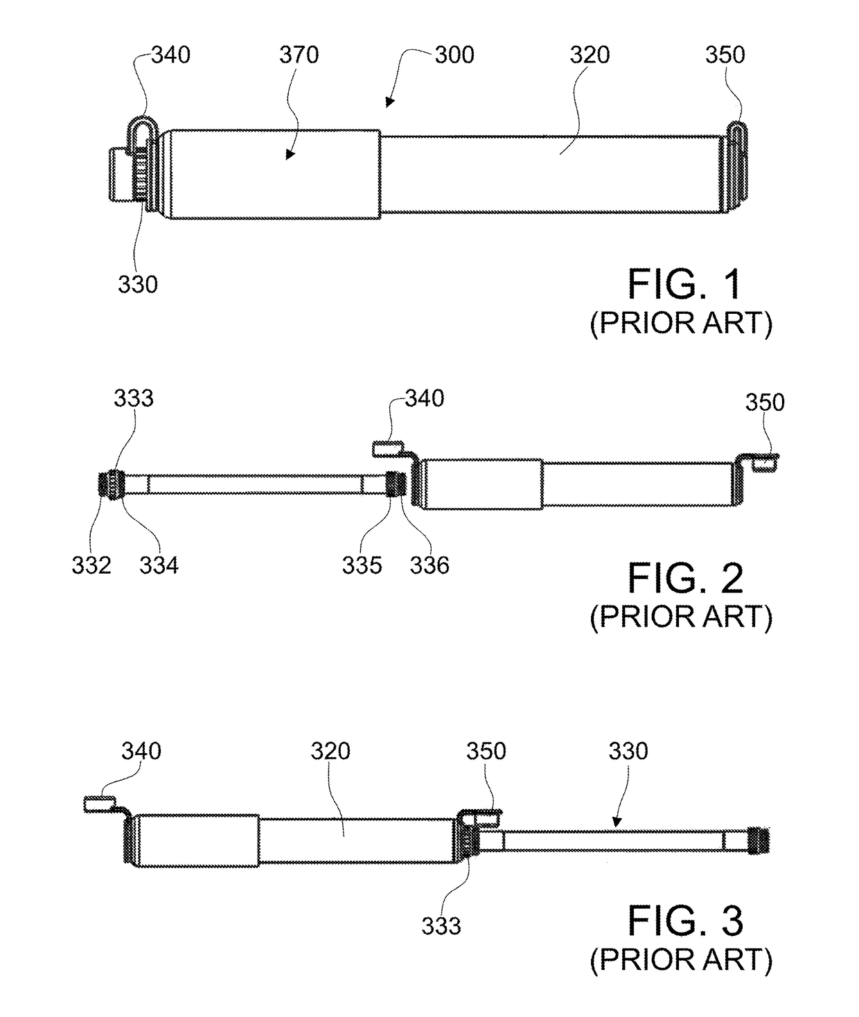
As shown in FIGS. 1-5 and described above, a typical prior art pump of this kind is unwieldy to use when starting from the storage configuration, and the effect of the pumping operation may not be satisfying.

Method used


Image

  • Bicycle pump
  • Bicycle pump
  • Bicycle pump

Examples


Embodiment Construction

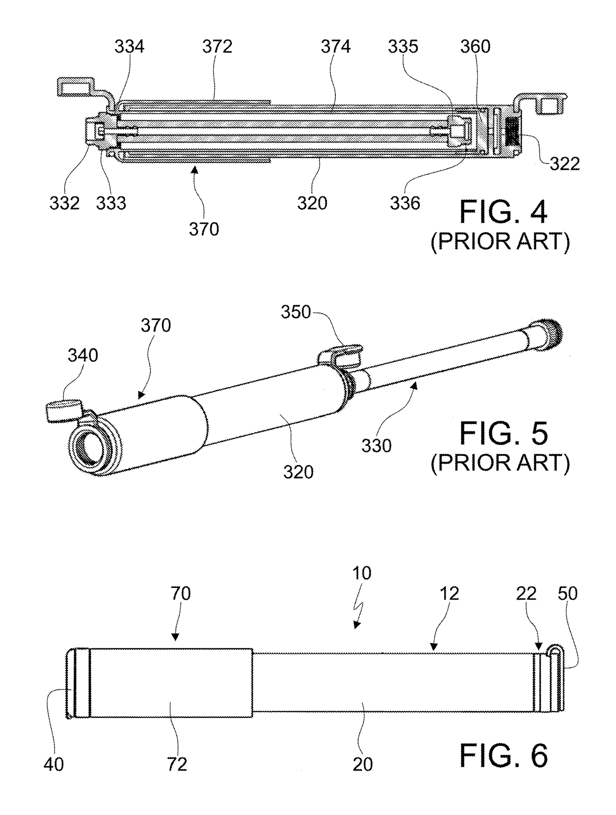
[0046]With reference to the schematic representation of FIGS. 6-17, a bicycle pump according to one embodiment of the invention is wholly indicated with 10. Note that various elements described herein may be omitted or combined in different embodiments.

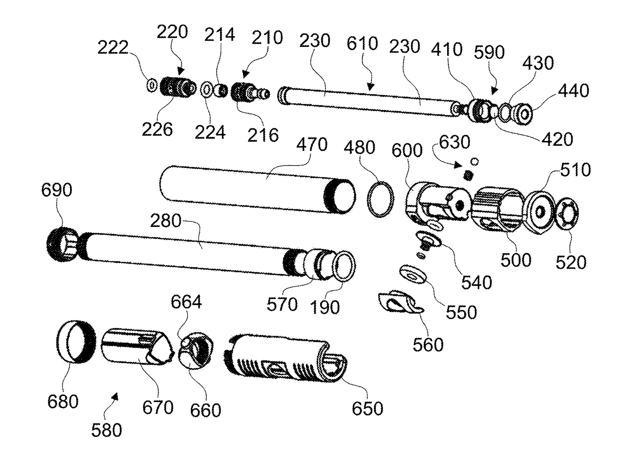
[0047]The bicycle pump 10 comprises a body assembly 12. The body assembly 12 includes an outer tube 20, and a head assembly 22. The outer tube 20 defines an air chamber 24, suitable for drawing air volumes from the outside and to transfer them into the tire through the tire valve, in a conventional manner.

[0048]The pump 10 further comprises a handle assembly 70. The handle assembly 70 is slidably associated with the body assembly 12. The handle assembly 70 includes a handle 260, a ring 270, an inner tube 280 and a piston 60; the piston 60 comprises an O-ring 190 for slidably sealing against outer tube 20's inner surface during pumping. Piston 60 is designed to allow O-ring 190 to unseal during the pull stroke, allowing air to refill t...


PUM


Abstract

A bicycle pump includes a pump body assembly, a handle assembly, a flexible hose assembly, and / or a magnet. The pump body assembly may include an outer tube, which defines an air chamber, and a head assembly with an air outlet opening. The handle assembly may slidably be associated with the body assembly, and include an inner tube and a piston, slidable inside the outer tube. The flexible hose assembly may be suitable to be stored inside the inner tube when the pump is not in use, and suitable to be connected to the air outlet opening during pumping. The magnet may connect the flexible hose assembly to the air outlet opening of the head assembly in a removable manner.

Description

BACKGROUND[0001]Technical Field[0002]The present invention relates to a bicycle pump.[0003]Related Art[0004]Many types of bicycle tire pumps are known, for example hand pumps. Each type of pump has some advantages and some disadvantages. One type of portable bicycle tire hand pump has a flexible hose assembly that is stored inside the telescoping tubes and screwed into place when not in use. One advantage of this type of pump is that, when not in use, the pump is more compact, and therefore easier to carry; another advantage is that the flexible hose allows pump motion with less risk of damaging the tire valve, with respect to pumps in which there is a direct connection between the pump head and the tire valve itself.[0005]To inflate a tire with this type of pump, the flexible hose assembly is first unscrewed from the handle assembly; then one end of the flexible hose is screwed into the pump body, and the other end is screwed onto the tire valve. When finished pumping, one end of t...

Claims


Application Information

Patent Timeline
IPC IPC(8): F04B33/00F04B39/12F04B53/10F04B39/00
CPCF04B33/005F04B53/102F04B39/121F04B39/0005F04B33/00F04B39/0016F04B39/14F04B53/121F04B53/22
Inventor HERMANSEN, FRANKWINEFORDNER, CARL
Owner CRANK BROS INC
Learn More