
Ferrule assembly and ferrule device

a technology of ferrule and assembly, which is applied in the direction of optics, instruments, optical light guides, etc., can solve the problems of difficult to flow adhesive over the whole fiber bore, the injection needle cannot reach the hollow, and the adhesive cannot be injected to a proper location, so as to achieve effective protection of the fiber, easy and smooth insertion

Active Publication Date: 2017-05-18
COMMSCOPE TELECOMM (SHANGHAI) CO LTD
View PDF8 Cites 4 Cited by
  • Summary
  • Abstract
  • Description
  • Claims
  • Application Information

AI Technical Summary

Benefits of technology

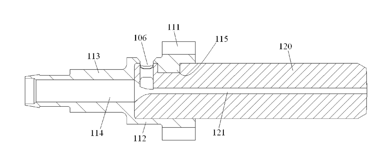
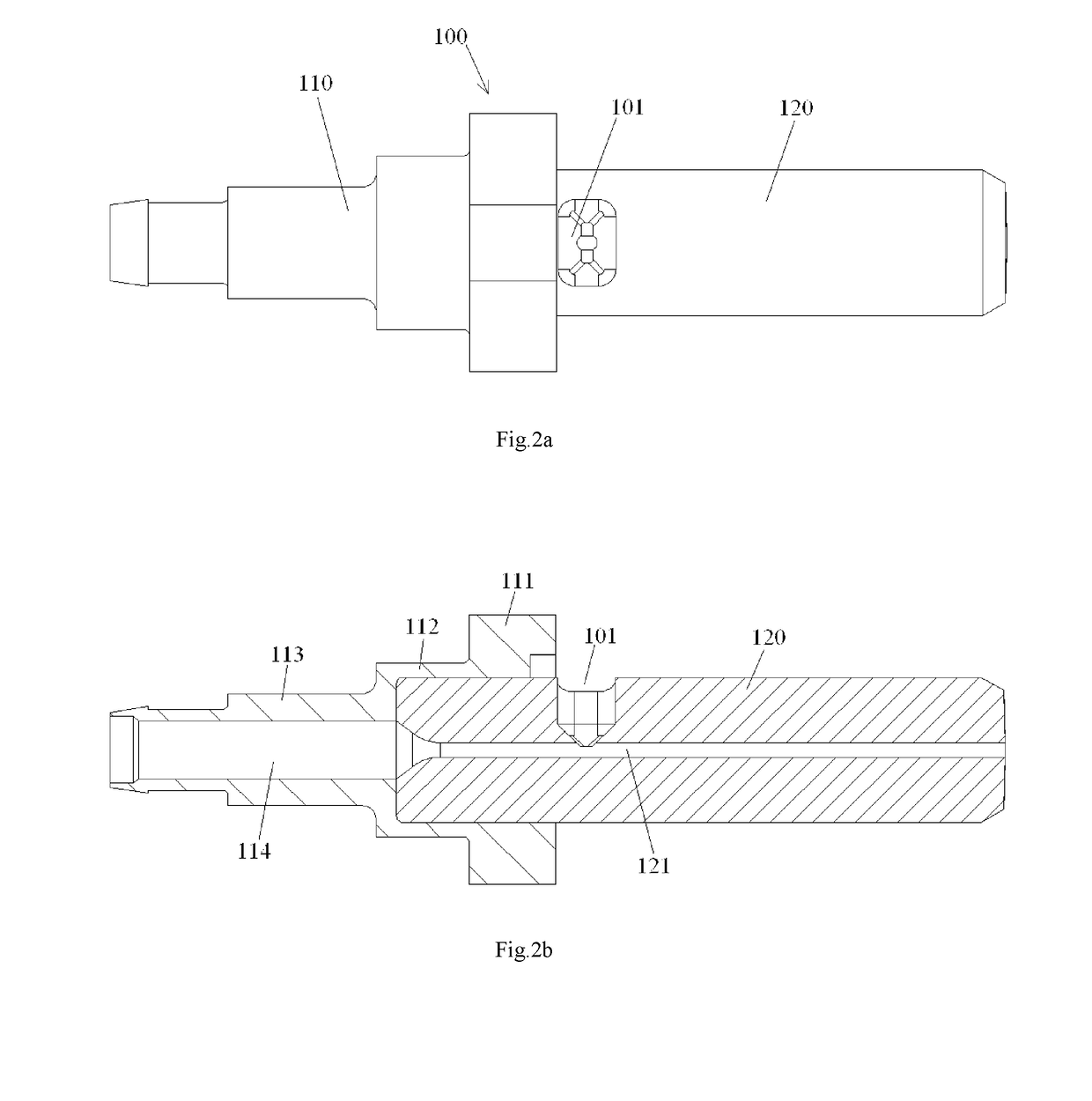
The invention provides a ferrule assembly that can protect fiber from damage and contamination during the process of inserting it into a ferrule and filling adhesive around it. The design includes an injection hole with an outer opening and a smaller inner opening to prevent adhesive injection needle from entering the fiber bore. Additional injection hole is formed in the external profile surface of the ferrule or the rear seat of the ferrule assembly to facilitate easy and smooth insertion of the fiber. Overall, the invention ensures the safe and smooth insertion of fiber into the ferrule assembly.

Problems solved by technology

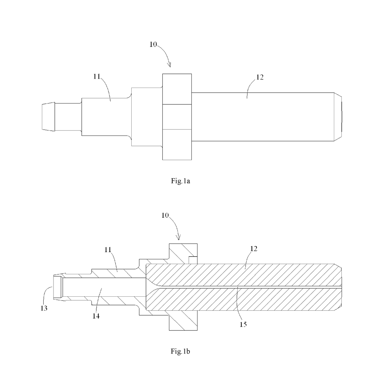
In order to avoid touching the fiber inserted into the ferrule assembly 10, sometimes, it needs to reduce the depth of the adhesive injection needle entering into the ferrule assembly 10, and it may cause a problem that the adhesive injection needle does not reach the hollow chamber 14, and the adhesive cannot be injected to a proper location in the ferrule assembly.
In this case, it is difficult for the adhesive to flow over the whole fiber bore 15 in the ferrule assembly 10.
It increases the resistance of inserting the fiber and may cause the fiber broken.
Furthermore, the adhesive adhered on the front end surface of the fiber decreases the optical performance of the fiber.

Method used


Image

  • Ferrule assembly and ferrule device
  • Ferrule assembly and ferrule device
  • Ferrule assembly and ferrule device

Examples


Embodiment Construction

[0075]Exemplary embodiments of the present disclosure will be described hereinafter in detail with reference to the attached drawings, wherein the like reference numerals refer to the like elements. The present disclosure may, however, be embodied in many different forms and should not be construed as being limited to the embodiment set forth herein; rather, these embodiments are provided so that the present disclosure will be thorough and complete, and will fully convey the concept of the disclosure to those skilled in the art.

[0076]In the following detailed description, for purposes of explanation, numerous specific details are set forth in order to provide a thorough understanding of the disclosed embodiments. It will be apparent, however, that one or more embodiments may be practiced without these specific details. In other instances, well-known structures and devices are schematically shown in order to simplify the drawing.

[0077]According to a general concept of the present inv...


PUM


Abstract

A ferrule assembly including: a ferrule formed with a fiber bore for receiving an optical fiber therein; and a rear seat connected to a rear end of the ferrule, wherein the rear seat is formed with a hollow chamber passing through the rear seat in a longitudinal direction and communicated with the fiber bore of the ferrule, and wherein an additional injection hole for injecting an adhesive into the ferrule assembly is formed in an external profile surface of the ferrule assembly, and directly communicated with the fiber bore of the ferrule or the hollow chamber of the rear seat. The ferrule assembly is configured to be adapted to insert a fiber before filling an adhesive and protect the fiber that has been inserted into the ferrule assembly during inserting the fiber or filling the adhesive into the ferrule assembly.

Description

CROSS-REFERENCE TO RELATED APPLICATION[0001]This application claims the benefit of Chinese Patent Application No. 201410309407.2 filed on Jul. 1, 2014 in the State Intellectual Property Office of China, the whole disclosure of which is incorporated herein by reference.BACKGROUND OF THE INVENTION[0002]Field of the Invention[0003]The present invention relates to an unfinished ferrule assembly and a fiber optic ferrule device for a fiber optic connector.[0004]Description of the Related Art[0005]FIG. 1a is an illustrative view of a single-fiber ferrule assembly (ferrule device) 10 of a fiber optic connector the in prior art; and FIG. 1b is a cross section view of the single-fiber ferrule assembly 10 shown in FIG. 1a. [0006]As shown in FIG. 1a and FIG. 1b, in the prior art, during manufacturing the single-fiber optic connector, the ferrule assembly 10 comprising a ferrule 12 and a rear seat 11 connected to a rear end of the ferrule 12 is usually used. The rear seat 11 may be a plastic me...

Claims


Application Information

Patent Timeline
Patent Type & Authority Applications(United States)
IPC IPC(8): G02B6/38
CPCG02B6/3861G02B6/3874G02B6/3882G02B6/3898G02B6/3881
Inventor TONG, ZHAOYANGLIN, LINLIU, LEI
Owner COMMSCOPE TELECOMM (SHANGHAI) CO LTD
Learn More