Method and device for encoding three-dimensional scenes which include transparent objects in a holographic system

a technology of holographic system and three-dimensional scene, which is applied in the field of holographic system three-dimensional scene encoding, can solve the problems of high computational load, inability to re-compute sound signals after head movements, and inability to achieve realistic auditory sensation without re-computing sound signals, so as to reduce the loudness of sound

Active Publication Date: 2017-02-09
SEEREAL TECHNOLOGIES
View PDF7 Cites 6 Cited by
  • Summary
  • Abstract
  • Description
  • Claims
  • Application Information

AI Technical Summary

Benefits of technology

[0060]In a preferred embodiment, at least one transparency value of at least one single object which is situated between an object point and the virtual observer position is considered in an amplified or weakened form in the computation of the apparent brightness values or the apparent brightness and colour values of individual object points in order to improve or reduce the visibility of that point.
[0070]Absorbing objects of the scene which are located between the sound sources and the listener ear decreases the loudness of the sound, resulting in a perception being quieter at the location of the ear of the observer than the sound source or acoustic source actual is. Sound reflecting surfaces or objects can generate additional virtual sound sources. Such sound being reflected can arrive later (i.e. under a different phase or different sound transit time or direction) compared to the sound of such a sound source arriving directly (i.e. without reflection) at the ear of the listener, thereby resulting in hall- or echo effects. This phase delay of the sound or the sound transit time is influenced by the velocity of sound in sound absorbing medium. Objects of the scene being capable of oscillation or vibration can be induced to oscillate / vibrate by incident sound, therefore resulting in virtual sound sources.

Problems solved by technology

The encoding can be achieved by generating aggregate holograms of the information of all object points, which can, however, easily cause a great computational load in particular with high-resolution display systems.
Because the image synthesis is a very complex process, the appearance of objects, surfaces and individual image points can change several times during the image synthesis.
This method has the disadvantage that only one brightness value or one brightness value and one colour value is determined for each involved ray which corresponds to a pixel on the display panel.
There are similar problems when simulating sound fields in a room considering its acoustic and geometric properties (auralisation).
It is a disadvantage here that it is only an aggregate signal that is rendered through the earphones.
A round tour in a virtual room is nevertheless possible when re-computing the auditory sensation for the changed position of the listener, but a realistic auditory sensation without re-computing the sound signals after head movements is not possible.

Method used


Image

  • Method and device for encoding three-dimensional scenes which include transparent objects in a holographic system
  • Method and device for encoding three-dimensional scenes which include transparent objects in a holographic system
  • Method and device for encoding three-dimensional scenes which include transparent objects in a holographic system

Examples


Embodiment Construction

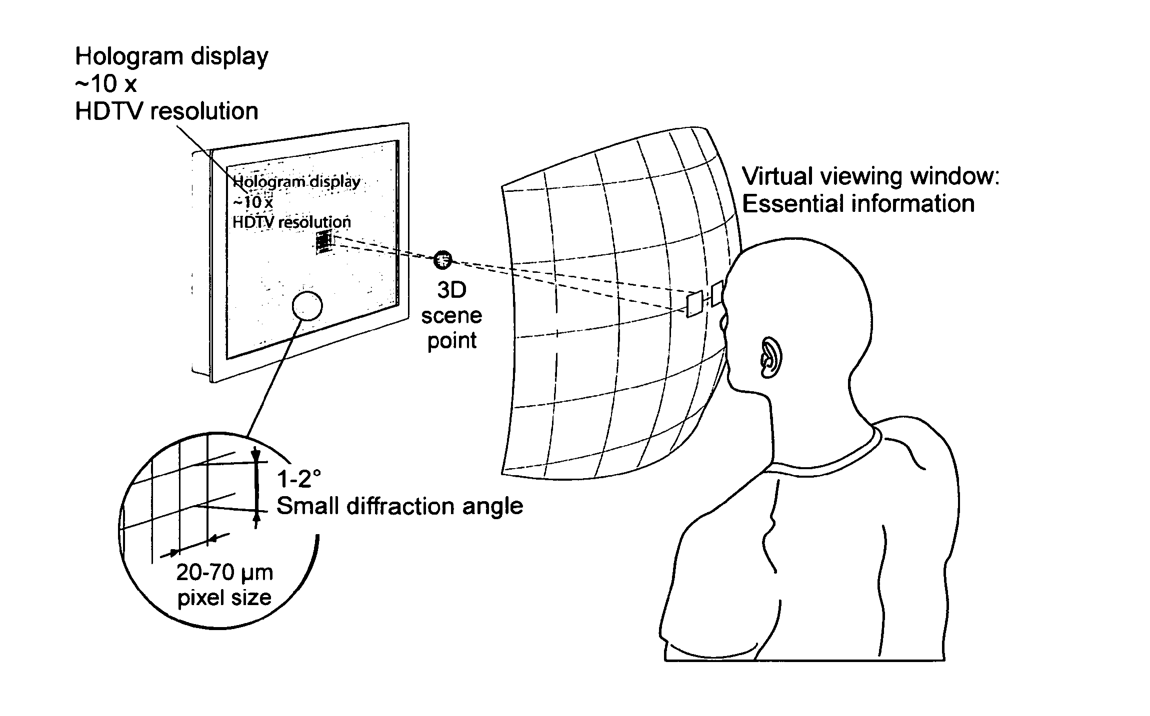
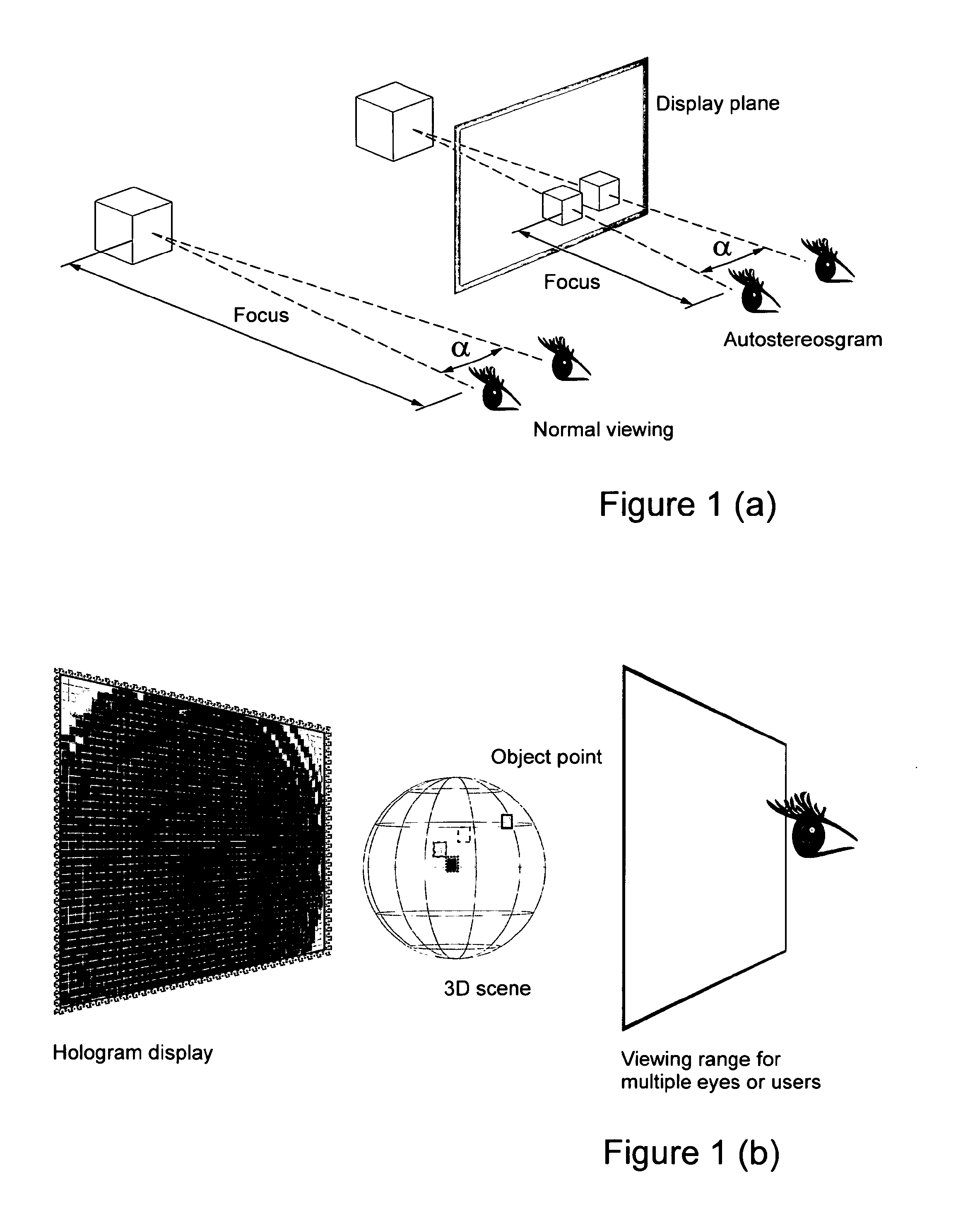
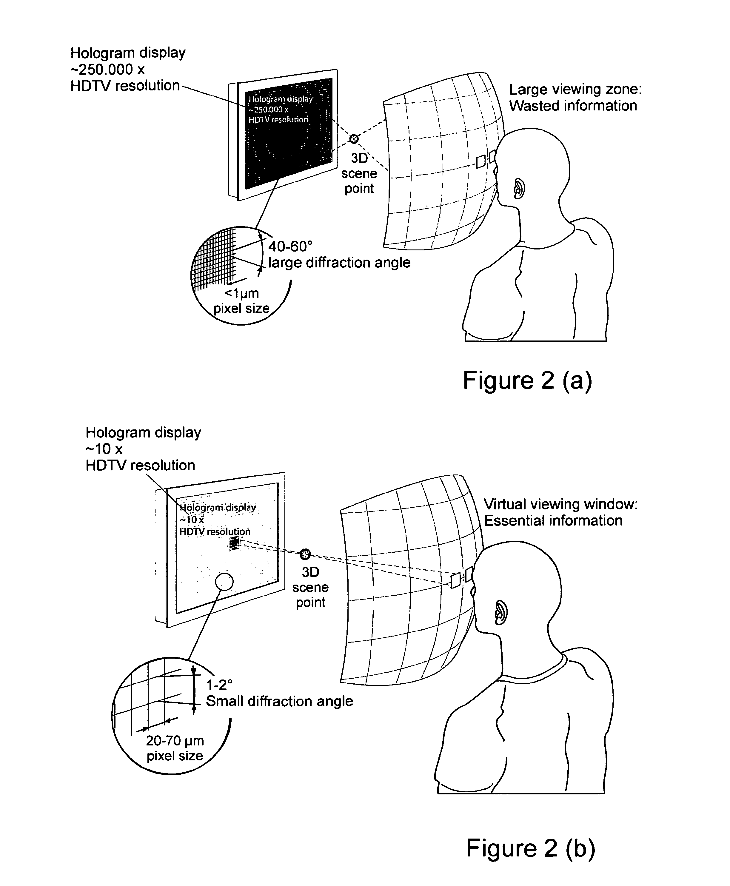
[0098]A view of a simple three-dimensional scene comprising an opaque and a transparent object is shown in a schematic presentation in FIG. 12. The three-dimensional scene which has to be reconstructed with a holographic system or a holographic display device (not shown) comprises an opaque object 200 and a transparent object 300. The two objects 200 and 300 can be divided into a plurality of individual object points (not shown in FIG. 12). A diffuse white light source (not shown) illuminates the three-dimensional scene uniformly from all directions. Light rays 101 to 110 of the light source are shown schematically in FIG. 12. The three-dimensional scene is reconstructed for an eye 400 of an observer. The location within the scene, from which the eye 400 of the observer apparently perceives the three-dimensional scene is determined to be the virtual observer position, also denoted with reference numeral 400. Object points being located on the averted side of the object 200 relative ...


PUM


Abstract

Method for computing the code for the reconstruction of three-dimensional scenes which include objects which partly absorb light or sound. The method can be implemented in a computing unit. In order to reconstruct a three-dimensional scene as realistic as possible, the diffraction patterns are computed separately at their point of origin considering the instances of absorption in the scene. The method can be used for the representation of three-dimensional scenes in a holographic display or volumetric display. Further, it can be carried out to achieve a reconstruction of sound fields in an array of sound sources.

Description

CROSS-REFERENCE TO RELATED APPLICATIONS[0001]This application is a continuation of U.S. application Ser. No. 13 / 638,782, filed Oct. 1, 2012, which claims the priority of PCT / EP2011 / 055144, filed on Apr. 1, 2011, which claims priority to European Application No. 10158996.8, filed Apr. 1, 2010, the entire contents of all of which are hereby incorporated in total by reference.BACKGROUND OF THE INVENTION[0002]The present invention relates to a method for computing encoding values of object points of three-dimensional scenes which include transparent objects. It further relates to a computing unit in which this method is implemented.[0003]The method can be applied for the computation of computer-generated holograms for holographic display systems or for the production of holograms (hard copy). It can further be used with other three-dimensional display systems where object points can be displayed separately in a staggered manner in space, such as volumetric displays.[0004]Generally, the ...

Claims


Application Information

Patent Timeline
Patent Type & Authority Applications(United States)
IPC IPC(8): G03H1/08G03H1/26G03H3/00G03H1/22
CPCG03H1/0808G03H1/2294G03H1/2249G03H1/26G03H3/00G03H2240/51G03H2001/2625G03H2001/2242G03H2210/36G03H2210/452G03H2226/02G03H1/2202G03H2210/12G03H2210/30G03H2210/63G03H2226/05G03H2240/56G03H1/08
Inventor ZSCHAU, ENRICOPFEIFER, NILS
Owner SEEREAL TECHNOLOGIES
Why Eureka
Try Eureka