
Piezoelectric pump and operating method thereof

a technology of pump and pump body, applied in the direction of pump control, pump components, positive displacement liquid engines, etc., to achieve the effect of enhancing fluid transmission efficiency and suppressing the backflow of fluid

Active Publication Date: 2016-12-29
KOGE MICRO TECH CO LTD
View PDF33 Cites 25 Cited by
  • Summary
  • Abstract
  • Description
  • Claims
  • Application Information

AI Technical Summary

Benefits of technology

This patent describes a piezoelectric pump that prevents fluid from flowing back and improves the efficiency of fluid transmission.

Problems solved by technology

Therefore, how to maintain the fluid to flow into the pump chamber through the inlet and flow out of the pump chamber through the outlet without occurrence of back flow when the piezoelectric vibrator actuates has become one of the current urgent problems to be solved.

Method used


Image

  • Piezoelectric pump and operating method thereof
  • Piezoelectric pump and operating method thereof
  • Piezoelectric pump and operating method thereof

Examples


Embodiment Construction

[0033]Reference will now be made in detail to the present preferred embodiments of the invention, examples of which are illustrated in the accompanying drawings. Wherever possible, the same reference numbers are used in the drawings and the description to refer to the same or like parts.

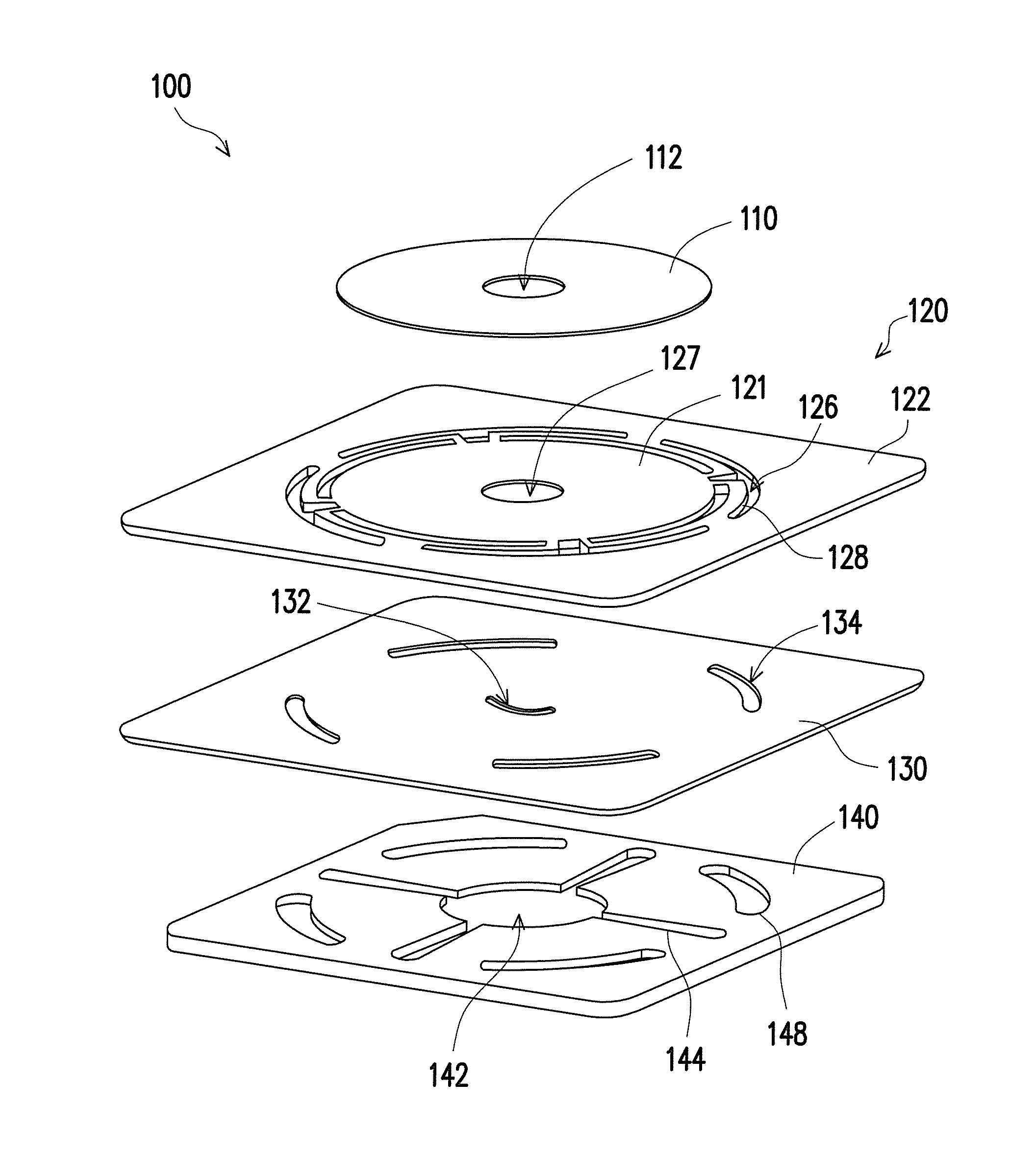
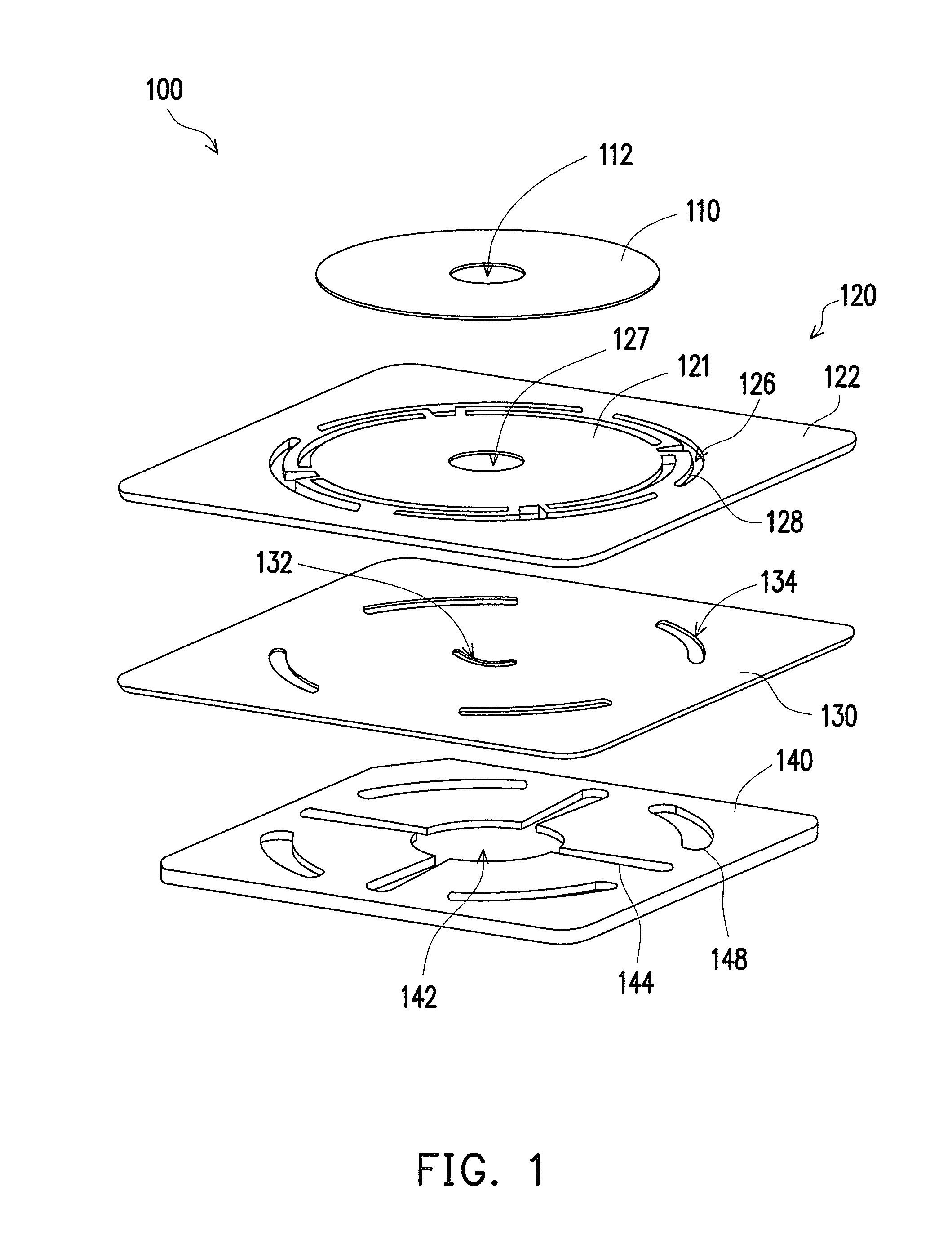
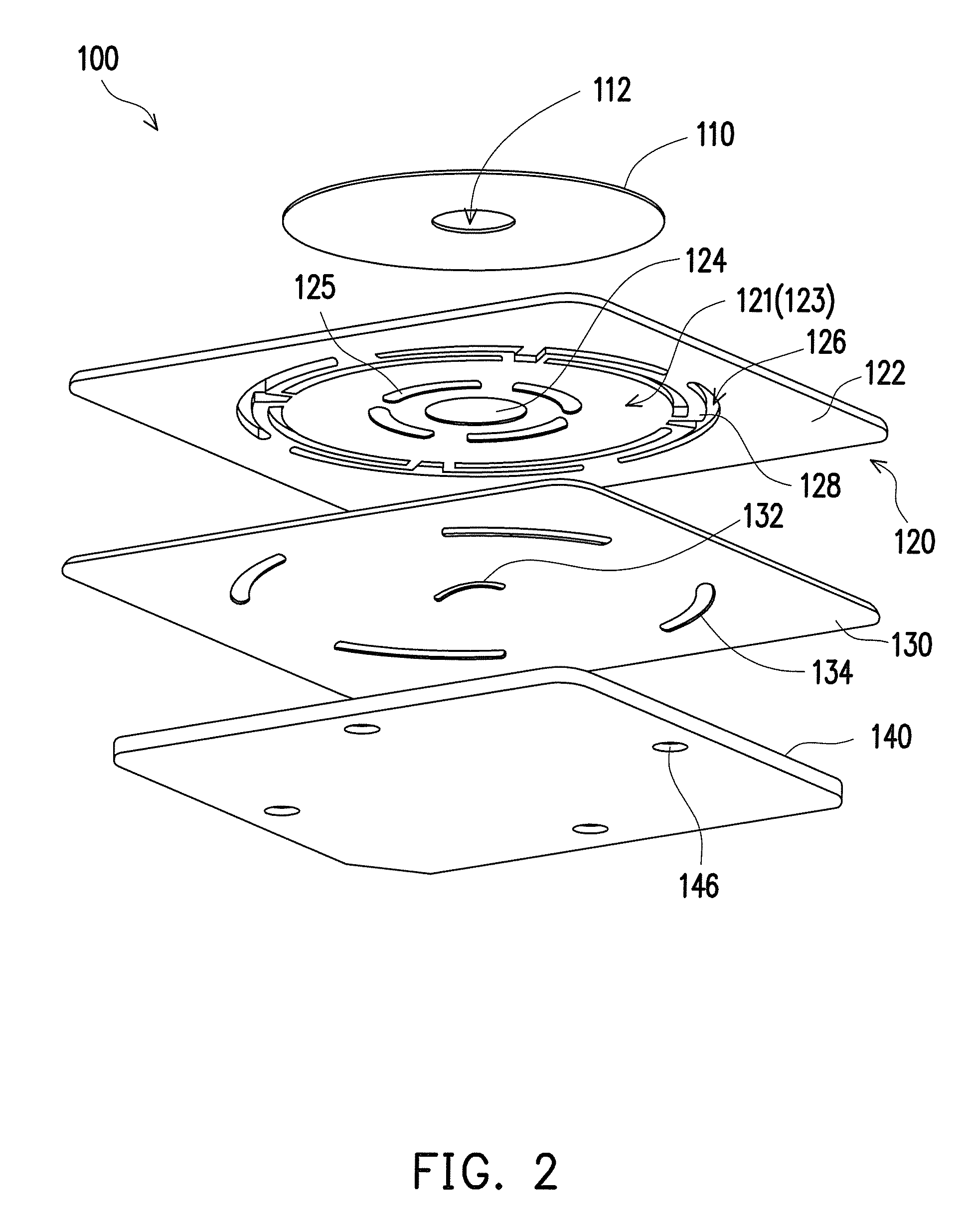
[0034]FIG. 1 is a schematic exploded view of a piezoelectric pump according to an embodiment of the disclosure. FIG. 2 is a schematic view depicted in FIG. 1 from another view angle. FIG. 3 is a schematic cross-sectional view showing the piezoelectric pump of FIG. 1 after assembled. FIG. 4 is a partially enlarged schematic view of FIG. 3. Referring to FIG. 1 through FIG. 4, the piezoelectric pump 100 of the embodiment includes a piezoelectric element 110, a vibrating piece 120, a valve 130 and a flow guiding member 140.

[0035]In the embodiment, the outer profile shape of the piezoelectric element 110 is a round shape and appears to be a sheet shape, and the piezoelectric element 110 includes a perfora...


PUM


Abstract

A piezoelectric pump includes a piezoelectric element, a vibrating piece, a valve and a flow guiding member. The vibrating piece has a central zone attached to the piezoelectric element, a peripheral zone, a first recess, a stopper and a position limiting wall both protruding from the first recess, and a through groove disposed between the central zone and the peripheral zone and connected through the first recess. The valve is attached to the peripheral zone and has a non-straight through slit. The flow guiding member is attached to the valve and has a second recess and a channel both recessed in the flow guiding member, and a through hole. The channel is connected through the second recess and the through hole. A projection of the second recess projected on the plane which the valve exists covers the non-straight through slit. An operating method of a piezoelectric pump is further provided.

Description

CROSS-REFERENCE TO RELATED APPLICATION[0001]This application claims the priority benefit of Taiwan application serial no. 104120510, filed on Jun. 25, 2015. The entirety of the above-mentioned patent application is hereby incorporated by reference herein and made a part of this specification.BACKGROUND OF THE DISCLOSURE[0002]1. Field of the Disclosure[0003]The disclosure relates to a piezoelectric pump and operating method thereof. More particularly, the disclosure relates to a piezoelectric pump and operating method thereof capable of suppressing back flow and improving transmission efficiency.[0004]2. Description of Related Art[0005]Piezoelectric pumps are novel sorts of fluid actuators, in which no drive motor is required and, implement fluid transmission merely via the inverse piezoelectric effect of the piezoelectric ceramics which make the piezoelectric vibrator deforms so that the deformation of the piezoelectric vibrator causes the volume change of the pump chamber, or trans...

Claims


Application Information

Patent Timeline
IPC IPC(8): F04B43/04F04B53/10
CPCF04B53/10F04B43/046F04B17/003F04B43/04
Inventor WU, CHUNG-HANYEN, YU-CHANG
Owner KOGE MICRO TECH CO LTD
Learn More