
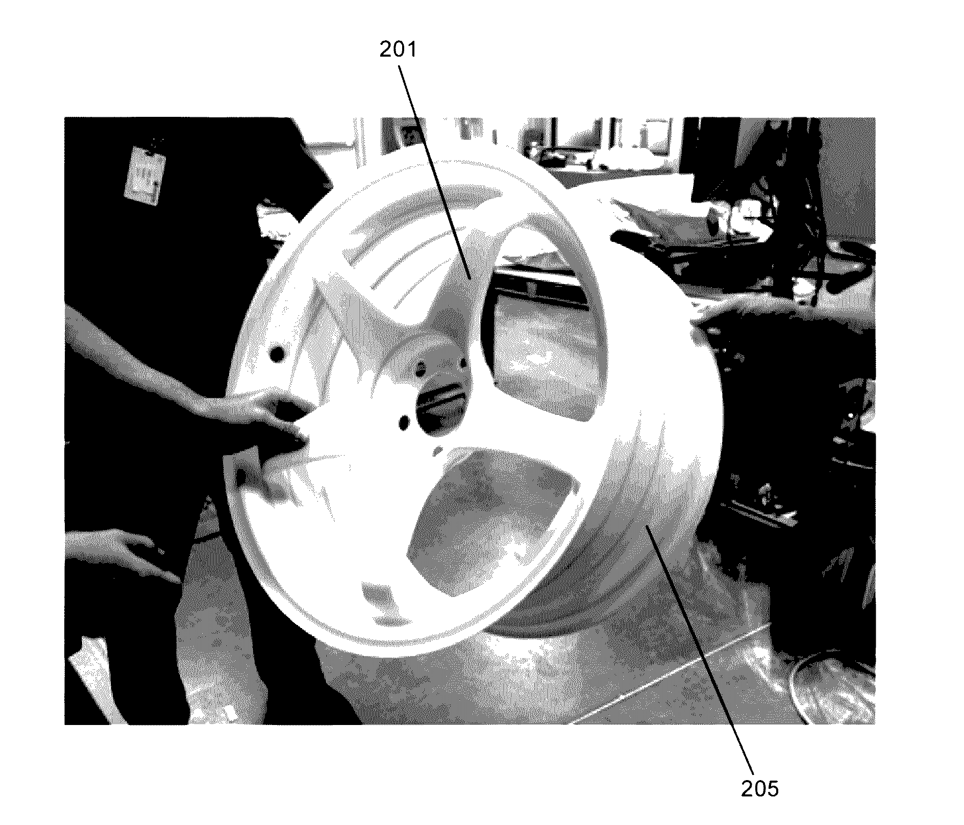
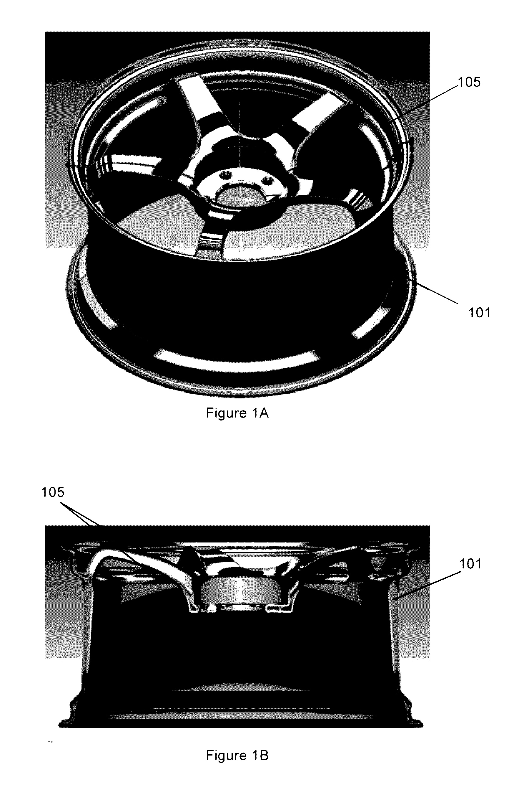
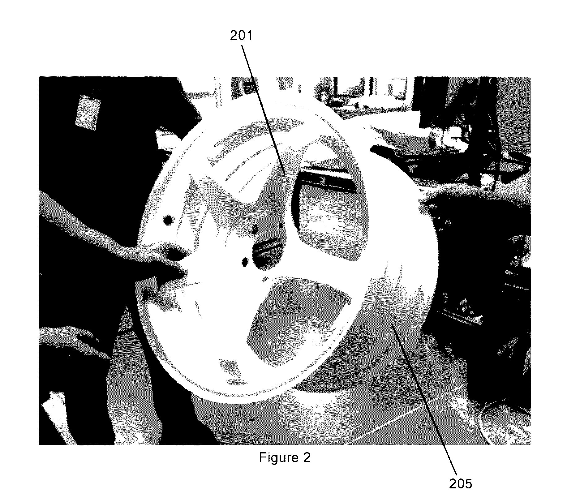
Molded wheel device

a technology of molded wheels and components, applied in the direction of wheel assembling tools, non-metallic wheel bodies, vehicle components, etc., can solve the problem that the approach may not handle making intricate features

Active Publication Date: 2016-12-01
QUIROZ JOSHUA
View PDF0 Cites 8 Cited by
  • Summary
  • Abstract
  • Description
  • Claims
  • Application Information

AI Technical Summary

Benefits of technology

The present invention is about a method for manufacturing a carbon fiber composite wheel. The technical effects of the invention include reducing the weight of motor vehicles parts by using carbon fiber, making intricate features easier, and improving the overall manufacturing process. The invention involves a method for making a carbon fiber composite wheel by placing carbon fiber fabric into a mold cavity and then curing it. The invention also includes a detailed description of the carbon fiber composite wheel and the process of making it. The invention is not limited to the specific methodology, compounds, materials, manufacturing techniques, uses, and applications described herein, as there may be other methods and variations of the invention that fit within the scope of the patent.

Problems solved by technology

Such approaches may not handle making intricate features since smaller details may be difficult to mold.

Method used


Image

  • Molded wheel device
  • Molded wheel device
  • Molded wheel device

Examples


Embodiment Construction

[0016]The present invention is best understood by reference to the detailed figures and description set forth herein.

[0017]Embodiments of the invention are discussed below with reference to the Figures. However, those skilled in the art will readily appreciate that the detailed description given herein with respect to these figures is for explanatory purposes as the invention extends beyond these limited embodiments. For example, it should be appreciated that those skilled in the art will, in light of the teachings of the present invention, recognize a multiplicity of alternate and suitable approaches, depending upon the needs of the particular application, to implement the functionality of any given detail described herein, beyond the particular implementation choices in the following embodiments described and shown. That is, there are modifications and variations of the invention that are too numerous to be listed but that all fit within the scope of the invention. Also, singular ...


PUM

PropertyMeasurementUnit
Temperatureaaaaaaaaaa
Weightaaaaaaaaaa
Pressureaaaaaaaaaa

Abstract

A method of manufacturing a wheel device including bonding a hub portion with lug holes and center bore hole, a spokes portion, and a barrel portion to generally form a mandrel or an inner frame of the wheel device. The inner frame is a scaled down size of the wheel device, in which a composite skin is wrapped around the inner frame to form an uncured wheel device. The uncured wheel device is encased inside a mold apparatus to cure. A cured wheel device of this method provides a wheel device with barrel, spokes, hub, lug holes and center bore hole molded into said wheel device without the use of a machine to carve out the spokes, hub, log holes or center bore hole.

Description

CROSS-REFERENCE TO RELATED APPLICATIONS[0001]Not Applicable.RELATED CO-PENDING U.S. PATENT APPLICATIONS[0002]Not Applicable.FEDERALLY SPONSORED RESEARCH OR DEVELOPMENT[0003]Not applicable.REFERENCE TO SEQUENCE LISTING, A TABLE, OR A COMPUTER LISTING APPENDIX[0004]Not Applicable.COPYRIGHT NOTICE[0005]A portion of the disclosure of this patent document contains material that is subject to copyright protection by the author thereof. The copyright owner has no objection to the facsimile reproduction by anyone of the patent document or patent disclosure for the purposes of referencing as patent prior art, as it appears in the Patent and Trademark Office, patent file or records, but otherwise reserves all copyright rights whatsoever.FIELD OF THE INVENTION[0006]One or more embodiments of the invention generally relate to motor vehicle parts. More particularly, the invention relates to a method for manufacturing a carbon fiber composite wheel.BACKGROUND OF THE INVENTION[0007]The following b...

Claims


Application Information

Patent Timeline
IPC IPC(8): B60B31/00B60B5/02
CPCB60B2310/52B60B2360/3416B60B2310/318B60B5/02B60B2310/204B60B31/00B60B2310/20B60B2310/321B60B2310/80
Inventor QUIROZ, JOSHUA
Owner QUIROZ JOSHUA
Learn More