Frame Structure for a Liquid Crystal Display
- Summary
- Abstract
- Description
- Claims
- Application Information
AI Technical Summary
Benefits of technology
Problems solved by technology
Method used
Image

Examples
embodiment 1
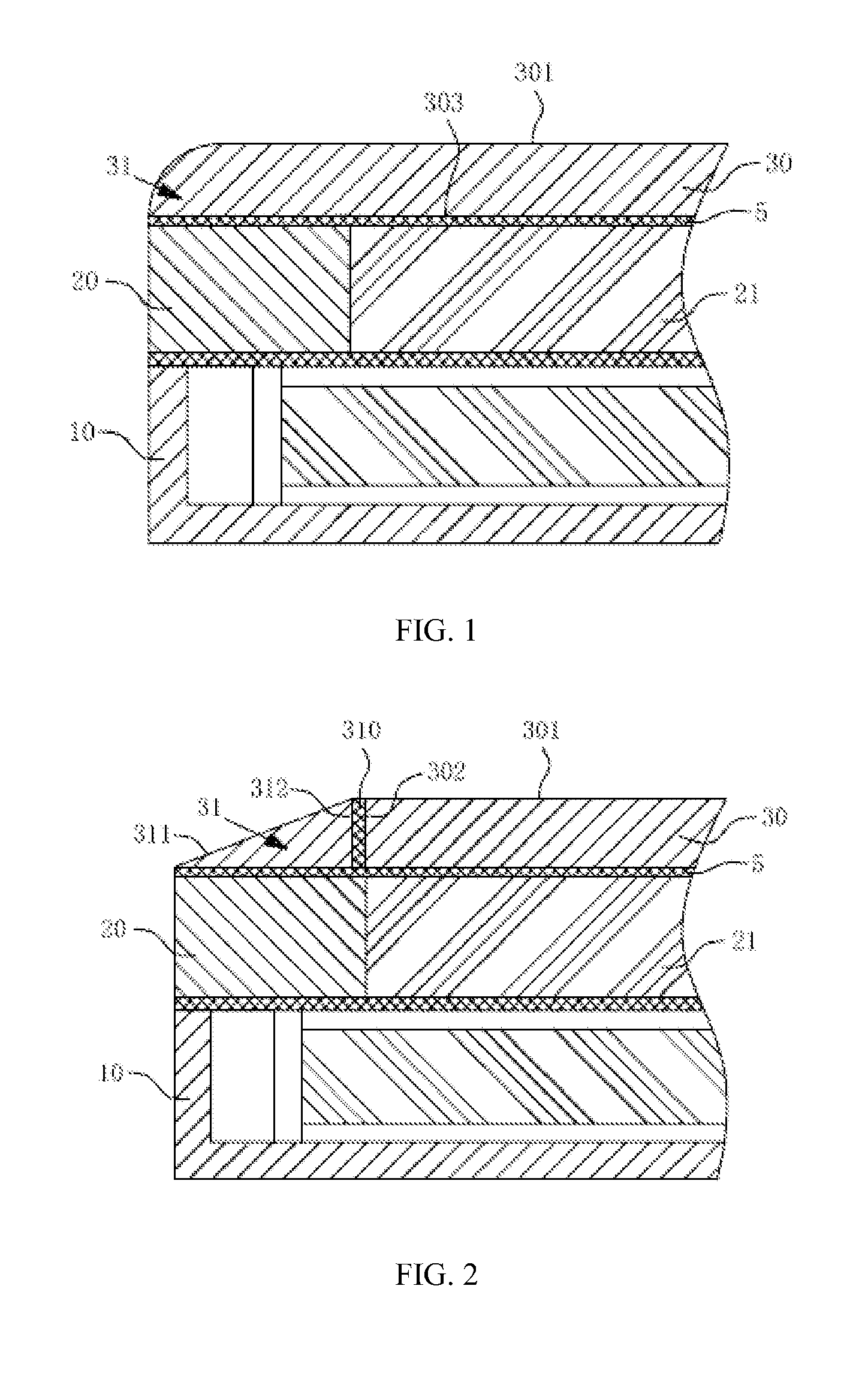
[0026]As shown in FIG. 1, the transparent structure 31 and the cover plate 30 constitute a one-piece structure in the embodiment. The frame 20 supports the transparent structure 31 and cover plate 30. The transparent structure 31 is disposed above the frame 20. The cover plate 30 comprises a first light-emitting surface 301 and a bottom surface 303. The transparent structure 31 is an arc surface which connects the first light-emitting surface 301 and the bottom surface 303. The cross-section of the acr surface is a sector shape. In particular, the arc surface of the transparent structure 31 reflects the light for display emitting from the liquid crystal panel 21. With respect to the area of the conventional cover plate 30 for displaying the light of the liquid crystal panel 21, the one-piece structure which is constituted by the transparent structure 31 and the cover plate 30 has a gareter display area. In the displaying mode, the light for display refracted by the transparent struc...
embodiment 2
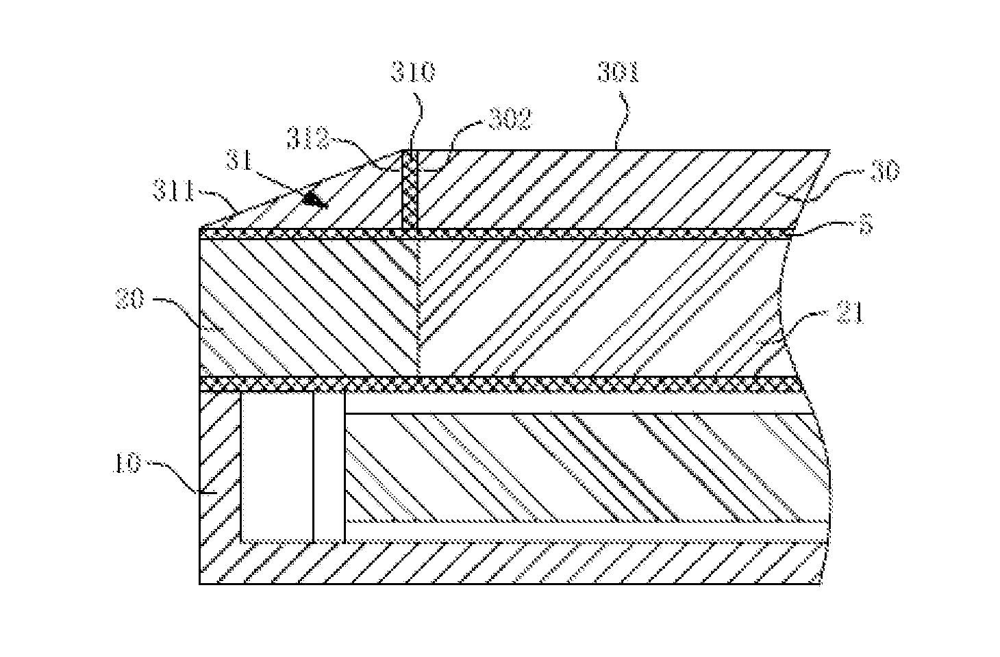
[0027]As shown in FIG. 2, the cover plate 30 and the transparent structure 31 are removable structure in this embodiment. The transparent structure 31 comprises a second light-emitting surface 311 and an inner wall 312, and the cover plate 30 comprises a first light-emitting surface 301 and an outer wall 302. The first light-emitting surface 301 connects with the second light-emitting surface 311 to form a display screen for an electronic device. The second light-emitting surface 311 is an inclined plane so that the cross-section of the transparent structure 31 is a triangular shape. The transparent structure 31 is a prism. Further, a transparent adhesive 310 is disposed between the inner wall 312 and the outer wall 302 in order to make the transparent structure 31 and the cover plate 30 fit closely without affecting the liquid crystal panel 21 to emit the light for display. Thus a removable structure is thereby formed.
[0028]Specifically, the transparent structure 31 is designed as ...
embodiment 3
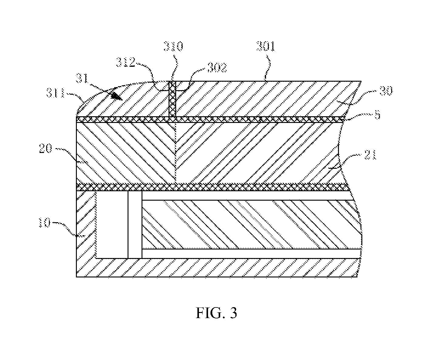
[0029]As shown in FIG. 3, the transparent structure 31 and the cover plate 30 are removable structure in this embodiment. The transparent structure 31 comprises a second light-emitting surface 311 and an inner wall 312, and the cover plate 30 at least comprises a first light-emitting surface 301 and an outer wall 302. The first light-emitting surface 301 connects with the second light-emitting surface 311 to form a display screen for an electronic device. The second light-emitting surface 311 is an acr surface such that the cross-section of the transparent structure 31 is a sector shape. The transparent structure 31 is a prism. Further, a transparent adhesive 310 is disposed between the inner wall 312 and the outer wall 302 in order to make the transparent structure 31 and the cover plate 30 fit closely without affecting the liquid crystal panel 21 to emit the light. Thus a removable structure is thereby formed.
[0030]Specifically, the transparent structure 31 is designed as a quarte...
PUM
 Abstract
Description
Claims
Application Information
 - R&D
- Intellectual Property
- Life Sciences
- Materials
- Tech Scout
- Unparalleled Data Quality
- Higher Quality Content
- 60% Fewer Hallucinations
Browse by: Latest US Patents, China's latest patents, Technical Efficacy Thesaurus, Application Domain, Technology Topic, Popular Technical Reports.
© 2025 PatSnap. All rights reserved.Legal|Privacy policy|Modern Slavery Act Transparency Statement|Sitemap|About US| Contact US: help@patsnap.com