Fault detection for bearings

a technology of bearings and faults, applied in the direction of machine parts testing, structural/machine measurement, instruments, etc., can solve the problems of bearings that tend to wear, various parts of bearings may be subject to failure, and one or more bearing parts may eventually fail

Active Publication Date: 2016-11-10
DEERE & CO
View PDF3 Cites 11 Cited by
  • Summary
  • Abstract
  • Description
  • Claims
  • Application Information

AI Technical Summary

Problems solved by technology

Generally, bearings tend to wear during use, such that one or more parts of the bearing may eventually fail.
Depending on the character of use and wear, various parts of a bearing may be subject to failure, including inner and outer races, rolling elements (e.g., balls or rollers), a bearing cage.
Unexpected failure of a bearing may prevent continuing operation of the affected device.
For example, where a bearing of an electric machine fails, the electric machine may be rendered inoperable until a replacement bearing has been installed.
As such, unexpected failure of bearings may lead to unexpected downtime for maintenance.
These methods may exhibit various deficiencies, however, including failure to detect faults sufficiently in advance of failure, failure to detect certain types of faults, failure to distinguish potential bearing failures from other system effects, and the need to install sensors (e.g., vibration sensors) that are not otherwise needed for control of the relevant system.

Method used


Image

  • Fault detection for bearings
  • Fault detection for bearings
  • Fault detection for bearings

Examples


Embodiment Construction

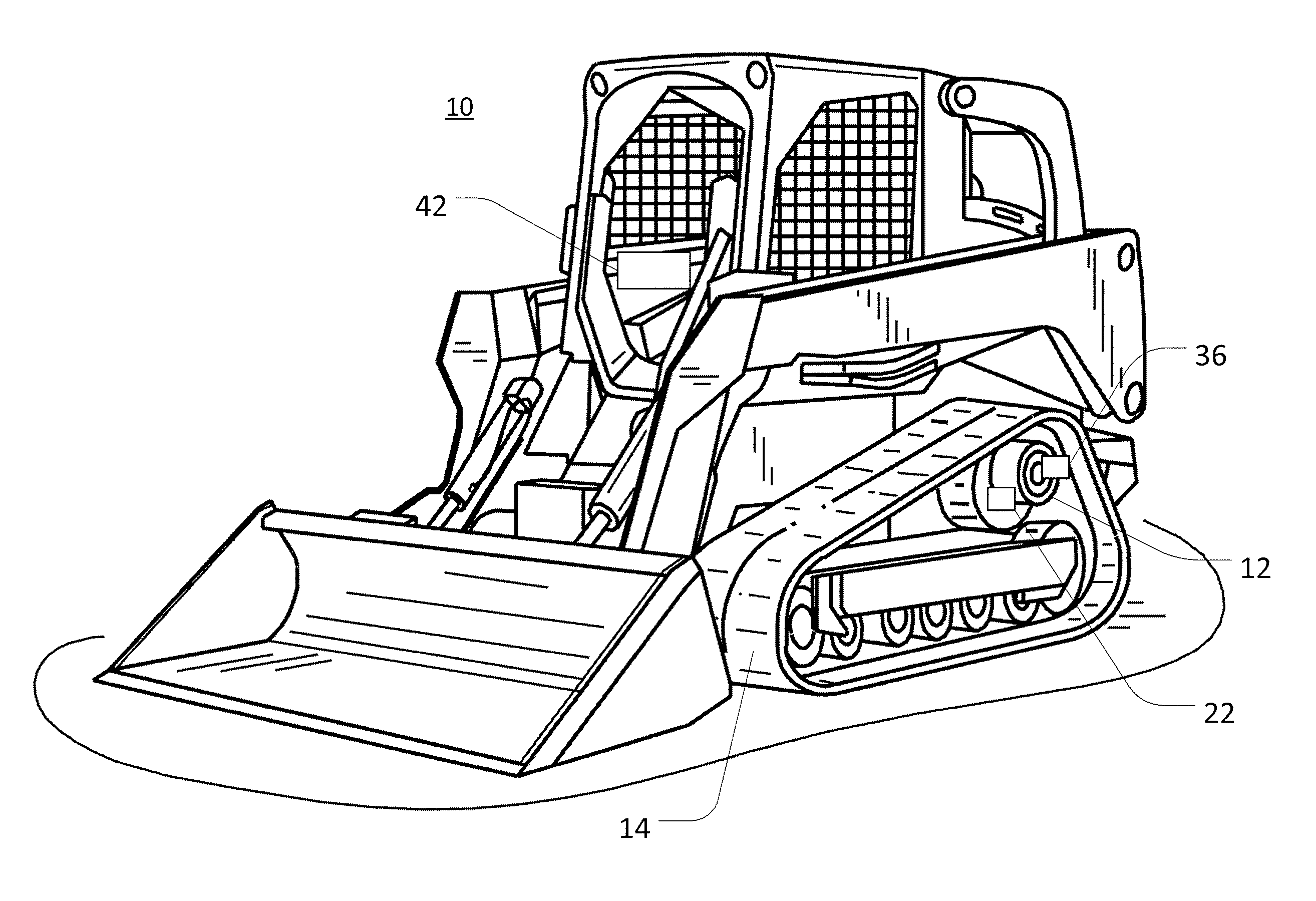
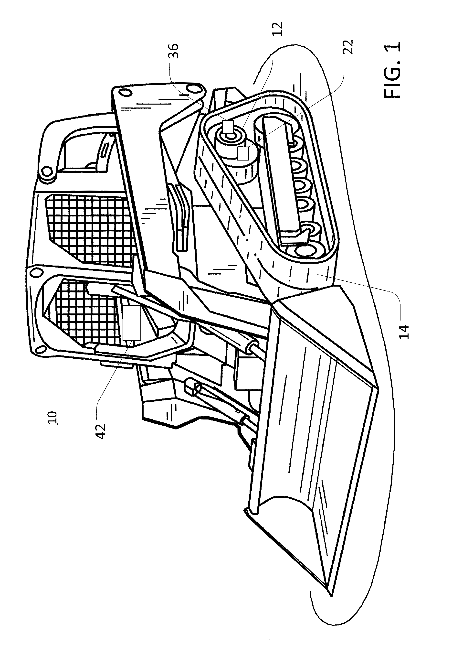
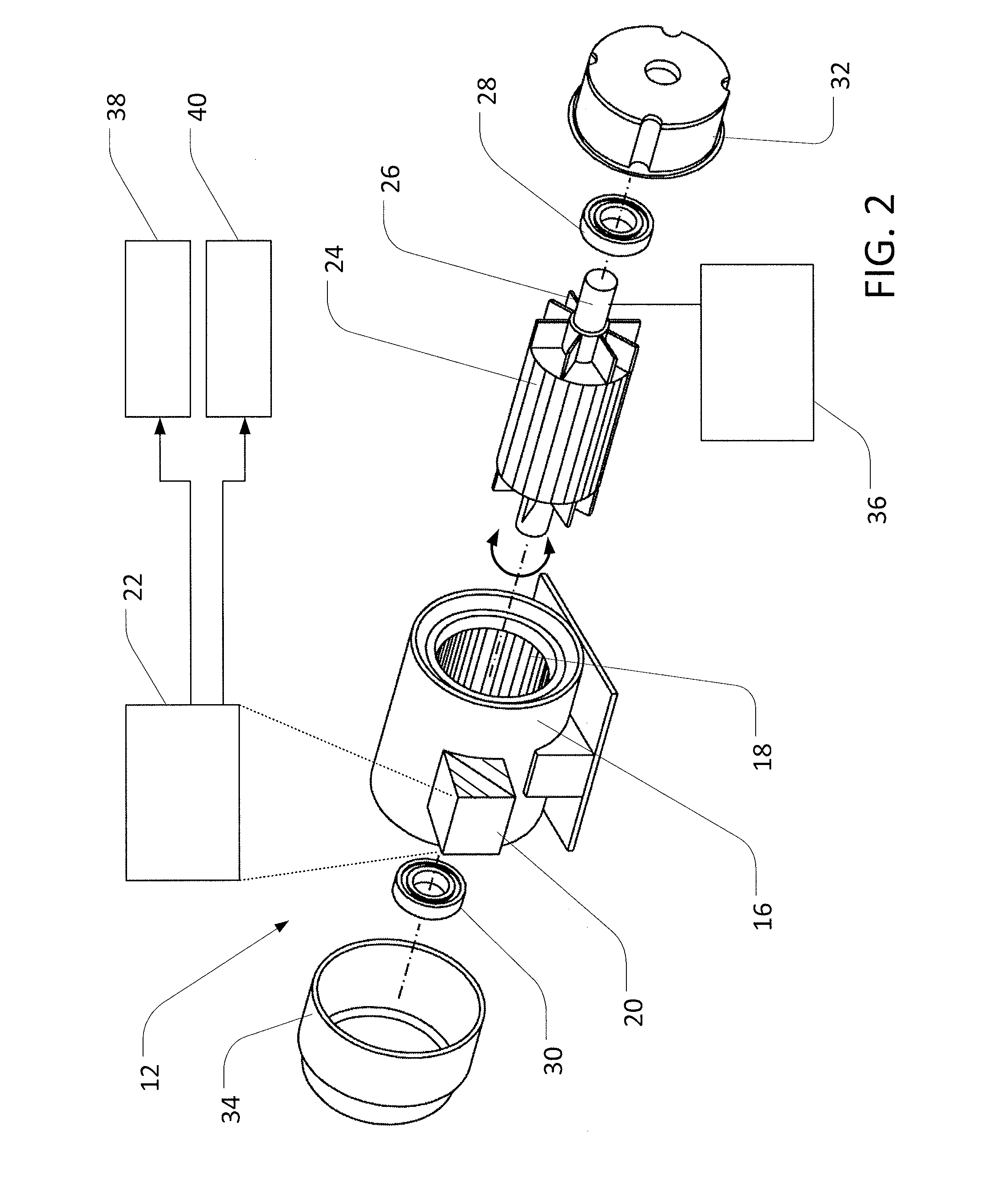
[0019]The following describes one or more example implementations of the disclosed bearing fault detection system, as shown in the accompanying figures of the drawings described briefly above.

[0020]As used herein, unless otherwise specified or limited, a “profile” includes a set of data with multiple values, indicating a relationship between at least two variables. For example, paired location and time values in a stored two-dimensional vector, with the pairs of values collectively indicating changes (or non-changes) in spatial locations of an object over time, may be viewed as representing a position profile for the object. Similarly, paired velocity and time values in a stored velocity vector, with the pairs of values collectively indicating changes (or non-changes) in the velocity of an object over time, may be viewed as representing a velocity profile for the object.

[0021]Also as used herein, unless otherwise specified or limited, a “peak” of a profile may include a local (or ab...


PUM


Abstract

A fault detection system is disclosed for predicting bearing failure in a system with a bearing-supported shaft. A position sensor may sense a position of the shaft as the shaft rotates. A controller may receive, from the position sensor, position data indicating a plurality of sensed positions of the shaft. The controller may determine a position or velocity profile for the shaft based upon the received position data and may determine a frequency profile based upon the position or velocity profile. The controller may identify a characteristic of the frequency profile, and identify an expected bearing failure based upon the identified characteristic.

Description

CROSS-REFERENCE TO RELATED APPLICATION(S)[0001]Not applicable.STATEMENT OF FEDERALLY SPONSORED RESEARCH OR DEVELOPMENT[0002]Not applicable.FIELD OF THE DISCLOSURE[0003]This disclosure relates to detection of faults in bearings, including bearings for electric and other machines.BACKGROUND OF THE DISCLOSURE[0004]Bearings may be used with various types of rotating machinery in order to provide for relatively smooth rotation. For example, bearings may support a shaft of an electric machine, such as a motor or generator, such that the shaft may deliver power from or to the electric machine. Bearings may also support rotating components, including other shafts, in various other applications.[0005]Generally, bearings tend to wear during use, such that one or more parts of the bearing may eventually fail. Depending on the character of use and wear, various parts of a bearing may be subject to failure, including inner and outer races, rolling elements (e.g., balls or rollers), a bearing cag...

Claims


Application Information

Patent Timeline
Patent Type & Authority Applications(United States)
IPC IPC(8): G01M13/04G01D5/12
CPCG01D5/12G01M13/04G01M13/045
Inventor VILAR, ZIMIN W.TREMEL, CHRIS J.PENCE, JACOB
Owner DEERE & CO
Why Eureka
Try Eureka