Systems and methods for producing laminates, layers and coatings including elements for scattering and passing selective wavelengths of electromagnetic energy

a technology of electromagnetic energy and transmission layer, applied in the direction of optical radiation measurement, instruments, spectrophotometry/monochromators, etc., can solve the problem of not being able to see inside the vehicle from the outside, providing substantially non-modifiable adverse transmission property of ambient light on the lighted side, and increasing the potential available energy collection or energy harvesting capacity of the particular object. , to achieve the effect of highly adaptable surface finishes

Pending Publication Date: 2016-10-20
FACE INT
View PDF1 Cites 8 Cited by
  • Summary
  • Abstract
  • Description
  • Claims
  • Application Information

AI Technical Summary

Benefits of technology

The patent describes a technique for creating layers and objects that appear opaque from the outside but are in fact transparent from the inside. This is achieved by using light scattering layers that allow for the transmission of energy / light and the reflection of selected wavelengths of light. The technique can enhance the appearance of embedded photovoltaic cells or photocells by coating or filming them to appear masked behind the layer. The resulting objects have a unique surface finish that can appear as any user-selectable color or pattern. Overall, this patent offers a way to incorporate embedded energy-generating components into objects without compromising their appearance.

Problems solved by technology

Thus, the principle of operation is to keep one side brightly lit rendering that side “difficult” to see through based on the principle that the reflected light masks visual penetration of the mirror from the brightly lit side.
While this may work in particular implementations, no one is fooled into believing that the observed mirrored panel is not provided for observation of the lit space from the other non-lit side.
Also, the very effect that is intended, in that a substantial portion of the incident light is reflected back from the “lighted” side of the mirror, provides a substantially non-modifiable adverse transmissive property of the ambient light on the lighted side of the panel through the panel.
It becomes difficult then to see inside the vehicle from the outside unless and until an observer gets very close to the vehicle and shades a portion of the film layer.
By doing so, the observer may be able to see through the vehicle window albeit that it may still be very heavily shaded, substantially defeating the purpose of the heavy tinting.
Here too, the configuration of the substantially darkened tinting adversely affects a light transmissive property from, for example, an outside of the vehicle to an inside of the vehicle, which is necessarily darkened or shaded in a non-discriminant manner.
These schemes are further limited by necessarily requiring that particular dimensions of a window area to be covered are known, and the window area must be available for the view-through vinyl to be applied thereto.
A difficulty is that conventional attempts to conceal, camouflage or otherwise hide the lenses of the cameras, or other image or energy receivers associated with particular sensors, generally indiscriminately and disadvantageously modify the characteristics of the electromagnetic energy passing through any concealing, camouflaging, or otherwise hiding layer.
In a case of visual, or near-visual, light passing through the concealment of a camera or sensor devices, this modification of the characteristics of the energy passing through the layer can, and generally does, adversely affect the operation of such devices in a concealed operational employment scenario.
A significant drawback to the wider proliferation of photocells used in a number of potentially beneficial operating or employment scenarios then is that such “required” installations, in many instances, adversely affect the aesthetics of the structure or object on which the photocells are to be mounted for use.
It is further known that the visual appearance of the photocells cannot be significantly altered from the dark presentation or composition provided by the facial surface without rendering the photocells significantly less efficient, or otherwise substantially degraded in their operation.
To date, however, the particular implementations discussed above, and other like implementations, are all constrained in their ability to be more-broadly adapted to a greater range of use cases based on their inherent limitations, the particular manufacturing processes by which objects including these particularized capabilities are formed, and certain attendant drawbacks in their use, particularly with regard to the manner in which the electromagnetic energy, including light in the visible and near-visible spectrum, is limited, filtered, occluded or otherwise modified as it passes from an energy- or light-incident side to an opposite side of the particular structure, structural component structural outer layer.

Method used


Image

  • Systems and methods for producing laminates, layers and coatings including elements for scattering and passing selective wavelengths of electromagnetic energy
  • Systems and methods for producing laminates, layers and coatings including elements for scattering and passing selective wavelengths of electromagnetic energy
  • Systems and methods for producing laminates, layers and coatings including elements for scattering and passing selective wavelengths of electromagnetic energy

Examples


Embodiment Construction

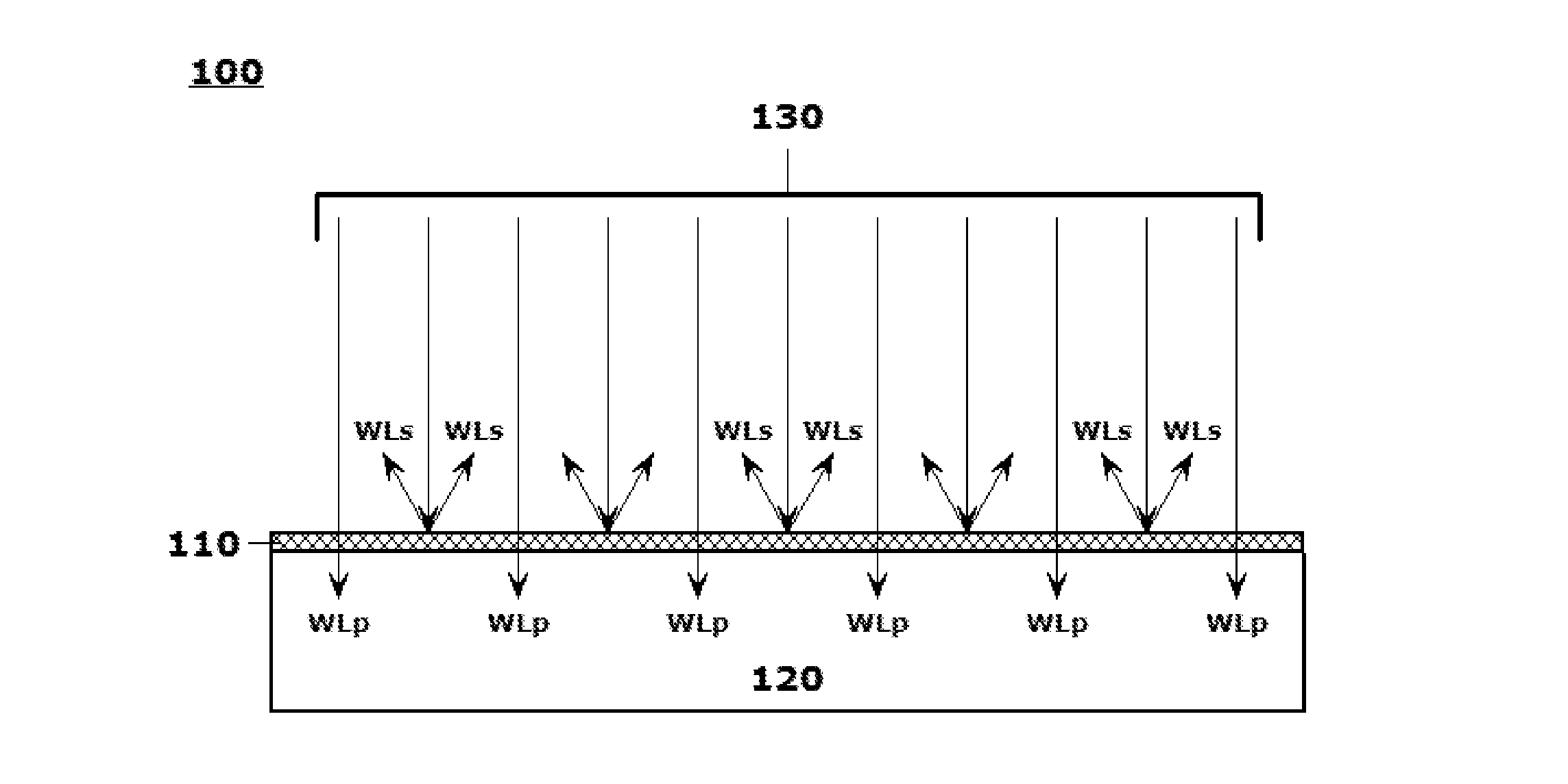
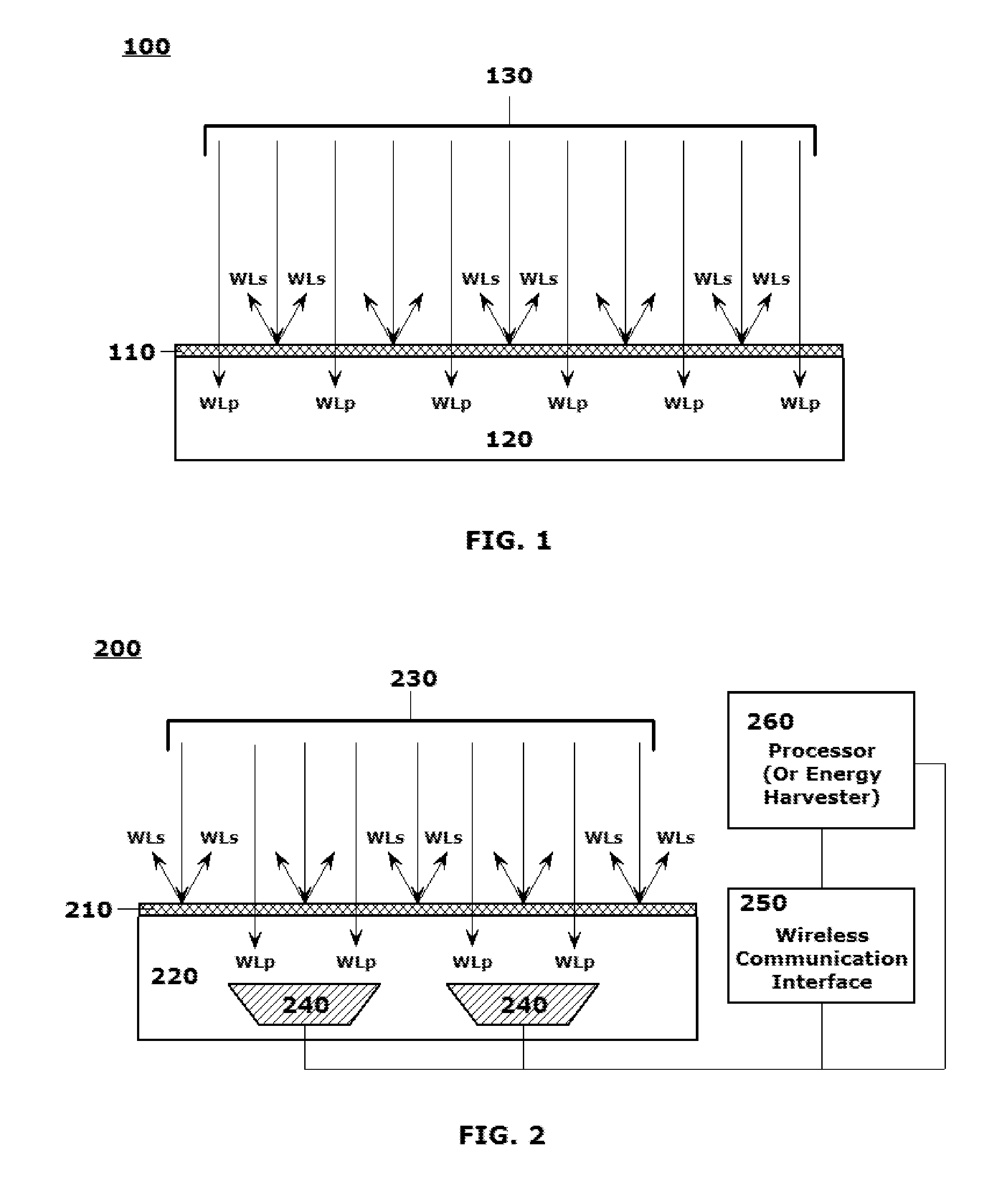
[0003]This disclosure relates to systems and methods for forming electromagnetic energy transmissive layers, which are particularly formed to selectively scatter specific wavelengths of electromagnetic energy while allowing remaining wavelengths to pass therethrough, including uniquely implementing optical light scattering techniques in such energy transmissive layers, and to objects, object portions, wall plates, lenses, filters, screens and the like that are formed of, or that otherwise incorporate, such transmissive energy-scattering layers.

2. Related Art

[0004]An ability to provide or promote selective transmission of electromagnetic energy, including light in the visual or near-visual radiofrequency (RF) spectrum through layers, materials, structures or structural components provides substantial benefit in a number of real-world use cases and applications. At a simplest level for electromagnetic energy in the optical, or near-optical, spectrum, windows, skylights and the like ar...


PUM

PropertyMeasurementUnit
diameteraaaaaaaaaa
particle sizesaaaaaaaaaa
sizesaaaaaaaaaa

Abstract

A system and method are provided for forming electromagnetic energy transmissive layers, which are particularly configured to selectively scatter specific and selectable wavelengths of electromagnetic energy, while allowing remaining wavelengths to pass therethrough. Processes are provided by which to form, or otherwise incorporate, one or more energy scattering layers, including uniquely implementing optical light scattering techniques in such energy scattering layers, and to objects, object portions, wall plates, lenses, filters, screens and the like that are formed of, or that otherwise incorporate, such transmissive energy-scattering layers. Refractive indices of particles fixed in a matrix are tunable in order that the finished layers provide an opaque appearance when viewed from an energy-incident excited by light in the visible spectrum. A color, pattern, texture or image of the scattering layer may be rendered according to an individual user's desires, the layers being substantially-transparent to light passing through layers.

Description

[0001]This application claims priority to U.S. Provisional Patent Application No. 62 / 147,573 entitled “Photovoltaic Cell and / or Photocell with Light Scattering Layer” by Clark D. BOYD et al., filed on Apr. 14, 2015, the disclosure of which is hereby incorporated by reference herein in its entirety. This application is related to U.S. patent applications Nos. [Applicant Reference No. SCV87-EE1-P2], entitled “Systems and Methods for Producing Objects Incorporating Selective Electromagnetic Energy Scattering Layers, Laminates and Coatings,” [Applicant Reference No. SCV87-EE1-A1], entitled “Systems and Methods for Implementing Selective Electromagnetic Energy Filtering Objects and Coatings Using Selectably Transmissive Energy Scattering Layers,” and [Applicant Reference No. SCV87-EE1-A2], entitled “Systems and Methods for Producing Objects Incorporating Selectably Active Electromagnetic Energy Filtering Layers and Coatings,” each of which is filed on a same date as this application, the...

Claims


Application Information

Patent Timeline
Patent Type & Authority Applications(United States)
IPC IPC(8): G02B5/02G02B5/26G02F1/19
CPCG02B5/0242G02B5/0268G02B5/26G02B5/0284G02F1/01G02F1/13G02F1/1675G02F1/1676G02F1/1685B60J3/04E06B9/24G01J2003/1213H01L31/02327G02B5/206H01L31/02161H01L31/02168G02B5/201B32B17/00B32B27/06B32B2255/00B32B2255/20B32B2255/26B32B2255/28B32B2307/404B32B2307/41B32B2307/412B32B2307/418B32B2457/12B32B2559/00G01J1/0488G02B5/0247G02B2207/123Y02E10/52G02F1/19B82Y20/00G02F2202/36G02B5/204G02F2203/10G02F2203/22G02F1/174B32B7/02G02F1/0018G02F1/0102G02B5/0263G02B5/0289G02B27/1006G02B1/10G02F1/0121H02S40/00G06F1/16
Inventor BOYD, CLARK D.FACE, BRADBURY R.SHEPARD, JEFFREY D.
Owner FACE INT
Why Eureka
Try Eureka