
Neurally triggered support ventilation during hfo ventilation

a support ventilation and hfo technology, applied in the field of ventilating systems, can solve the problems of insufficient gas supply of bias systems, inconvenient operation, and inability to accurately control the flow rate of air,

Active Publication Date: 2016-08-11
MAQUET CRITICAL CARE
View PDF8 Cites 9 Cited by
  • Summary
  • Abstract
  • Description
  • Claims
  • Application Information

AI Technical Summary

Benefits of technology

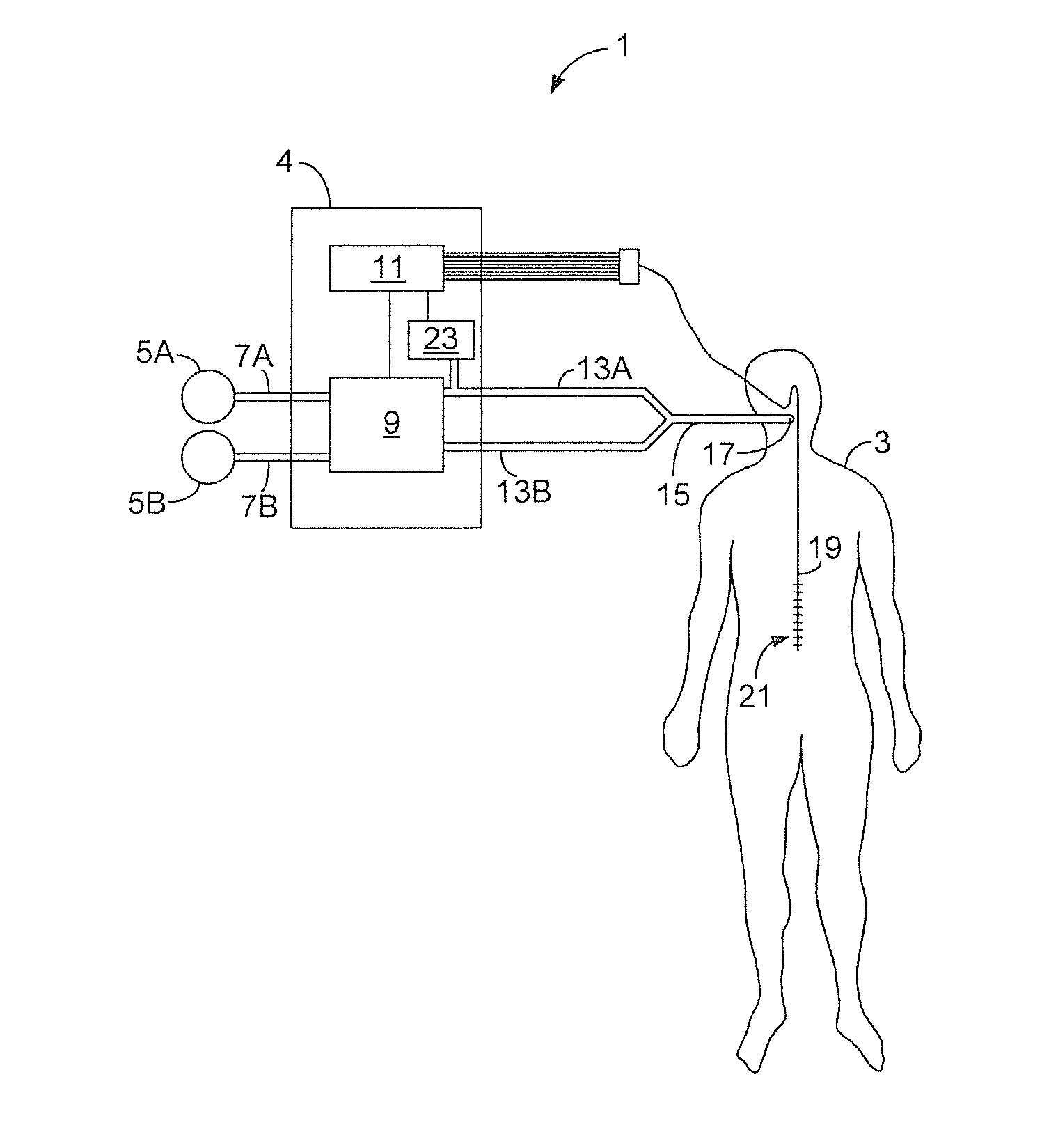
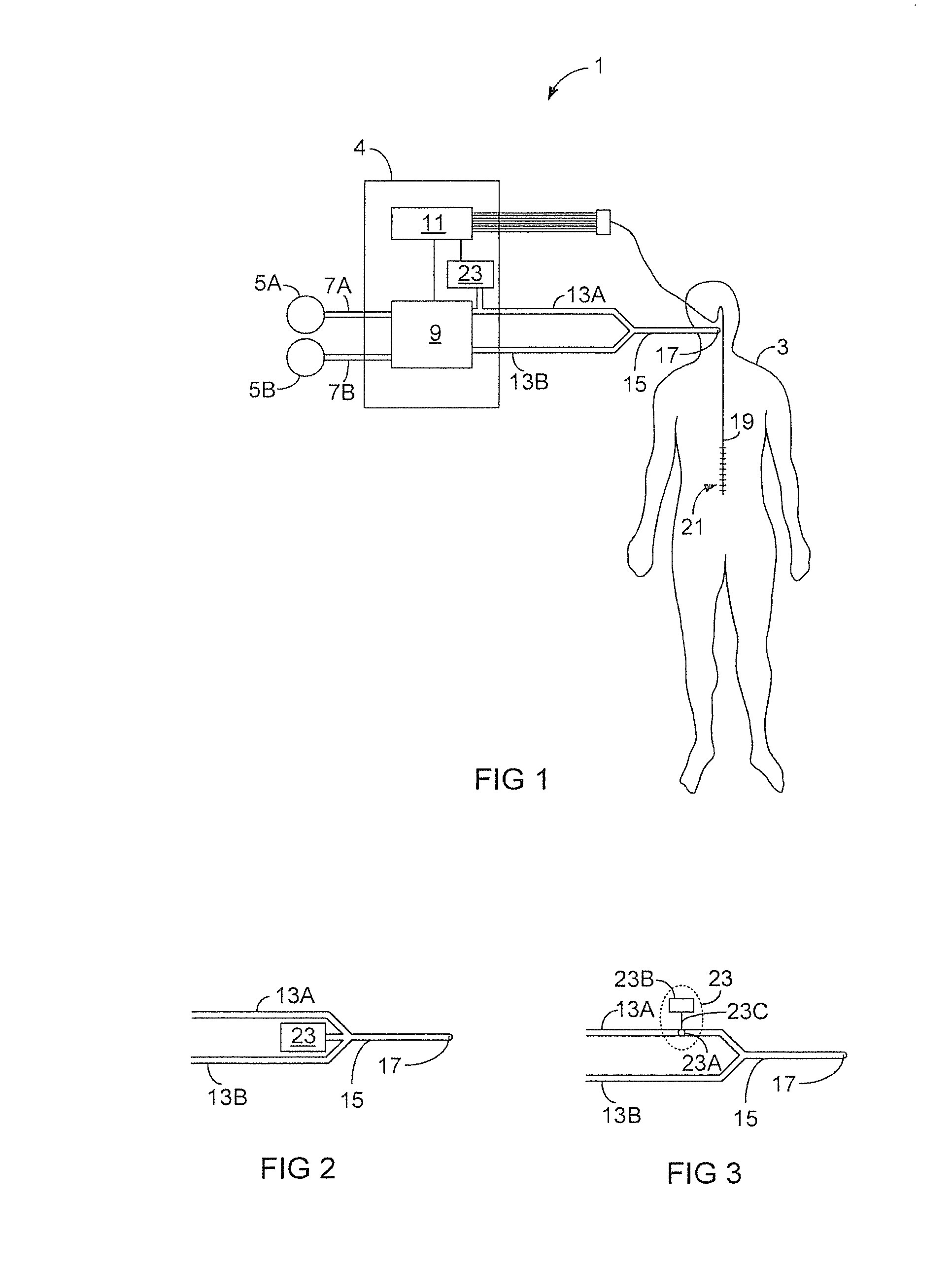
The invention provides a system for ventilating patients using high frequency pressure oscillations (HFV). The system uses neural triggering of gas delivery, which helps to distinguish between patient effort and the ongoing HFV ventilation. This allows for a more precise and robust way of providing accurate support ventilation during HFV ventilation. Additionally, the control unit can control both the delivery of normal breaths and the high frequency oscillation, making the overall ventilation of the patient meet their respiratory needs. The system also allows for switching between different modes of ventilation, including NAVA and HFNAVA.

Problems solved by technology

The bias supply of such systems is usually insufficient to supply sufficient gas to a patient if the patient should attempt a spontaneous breath.
The proposed combination of HFV ventilation and pneumatically (flow or pressure) triggered ventilation support may, in certain circumstances and in certain types of ventilation systems, have the disadvantage of being imprecise due to the difficulty of accurately identifying and measuring the changes in flow or pressure caused by the patient's effort to breathe within the high frequency pressure oscillations caused by the HFV ventilator.

Method used


Image

  • Neurally triggered support ventilation during hfo ventilation
  • Neurally triggered support ventilation during hfo ventilation

Examples


Embodiment Construction

[0029]The present invention strives to solve the problem of how to provide patient-triggered support ventilation to a spontaneously breathing patient during ongoing high frequency ventilation (HFV). As described above, HFV is a ventilation mode in which very small tidal volumes are delivered at high frequency, typically in the frequency range of 5 to 20 Hz. The rapidly fluctuating pressure in HFV systems makes it difficult to implement precise and robust pneumatic triggering of the support ventilation.

[0030]Relevant parameters defining the characteristics of the HFO ventilation include MAP (mean airway pressure), the oscillation frequency and the amplitudes of the oscillating pressure profile. As well known in the art, there are several subcategories of HFV. One subcategory of HFV is high frequency oscillatory ventilation (HFOV), sometimes also referred to as active high frequency ventilation (HFV-A). In HFOV, the oscillating pressure profile applied to the patient oscillates betwee...


PUM


Abstract

A ventilation system for providing patient-triggered support ventilation to a spontaneously breathing patient during ongoing HFV ventilation has a pneumatic unit for delivery of breathing gas to the patient in response to an effort to breathe by the patient, a control computer for controlling the delivery of breathing gas by said pneumatic unit, and an oscillator for superimposing high frequency oscillation onto the breathing gas. The system further includes a bioelectric sensor that measures a bioelectric signal indicative of the patient's efforts to breathe, and the control computer is configured to control the delivery of breathing gas in response to the patient's effort to breathe, based on this bioelectric signal. The ventilation system is hence designed for neurally triggered support ventilation during ongoing high frequency ventilation, HFV, which makes the trigger mechanism of the ventilation system more precise and robust compared to trigger mechanisms of known ventilation systems capable of providing support ventilation during ongoing HFV ventilation.

Description

BACKGROUND OF THE INVENTION[0001]1. Field of the Invention[0002]The present invention relates to a ventilation system for providing patient-triggered ventilatory support to a spontaneously breathing patient during ongoing high frequency ventilation (HFV) of the patient.[0003]2. Description of the Prior Art[0004]HFV ventilators supply breathing gas to the airways of a patient via a patient circuit from a frequency of approximately 150 breaths per minute up to 900 breaths per minute or more, and with tidal volumes significantly less than required during spontaneous breathing, typically at or below anatomical dead-space volumes. This is in marked contrast to a conventional mechanical ventilator which typically supplies breathing gas to the patient circuit at a frequency and with a tidal volume close to the values during spontaneous breathing.[0005]An HFV ventilator generally comprises an oscillator which is connectable in gas communication with one end of the gas tubing of a patient ci...

Claims


Application Information

Patent Timeline
Patent Type & Authority Applications(United States)
IPC IPC(8): A61M16/00A61B5/00A61B5/0492A61B5/296
CPCA61B5/0488A61M2205/3303A61B5/4836A61M16/12A61M2202/0208A61M2205/3331A61M2210/1014A61M2210/1021A61M2210/105A61M2230/08A61M2230/60A61M16/0069A61B5/0492A61B5/6852A61M16/0096A61B5/389A61B5/296
Inventor LARSSON, AKELONCAR, MARIOCARDELIUS, ERIK
Owner MAQUET CRITICAL CARE
Learn More