
Method for autostereoscopic projection displays

a projection display and autostereoscopic technology, applied in the field of autostereoscopic projection displays, can solve the problems of high cost, image registration problem, eye of viewer and projection lens, and inability to occupy the same space, etc., and achieve the effect of creating discrete viewing windows, and avoiding the formation of a separate viewing window

Inactive Publication Date: 2016-07-21
KOC UNIVSI
View PDF2 Cites 0 Cited by
  • Summary
  • Abstract
  • Description
  • Claims
  • Application Information

AI Technical Summary

Benefits of technology

This invention improves on traditional autostereoscopic projection displays by using two projectors instead of an array, which reduces cost and complexity. The viewer can change position without losing 3D vision or needing distortion correction. The projected images always overlap on the screen without needing translation.

Problems solved by technology

In order to see the projected image, the viewer must look through the created exit pupil, but it is impossible for two objects, eye of the viewer and projection lens, to occupy same position in space.
In multiple projector method, using many projectors will cause high cost, complex system structure, and image registration problem.
In the case of moving projectors, image registration problem, which is the problem of projecting images on the substantially overlapping areas of the screen, and correcting the image distortions, will occur in every movement of projectors.
Another problem with the multiple projector method and the parallax barrier method is that they create discrete viewing windows.
Thus, when the viewer changes its position, viewer experiences discrete transitions between viewing windows, and it causes unnatural 3D experience.

Method used


Image

  • Method for autostereoscopic projection displays
  • Method for autostereoscopic projection displays
  • Method for autostereoscopic projection displays

Examples


Embodiment Construction

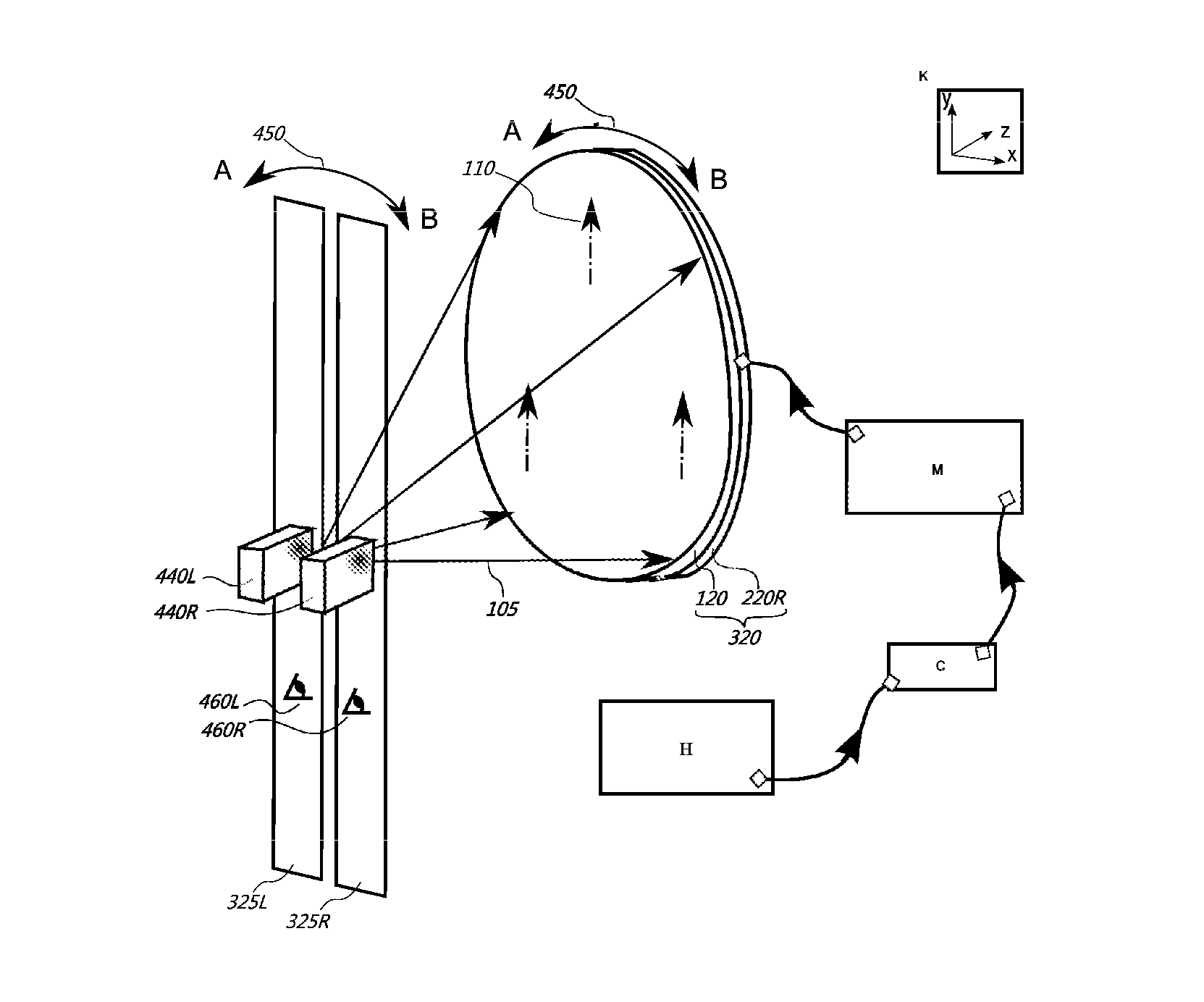
[0027]The present invention is in the field of autostereoscopic displays. It relates to a method of forming dynamic exit pupils (325) by a transfer screen (320) according to the viewer's position, and presenting the stereo images to the viewer. By the present invention, the viewer perceives stereo images in a comfortable viewing field (990) without need of any glasses, or so.

1) Forming Viewing Slits by the Transfer Screen

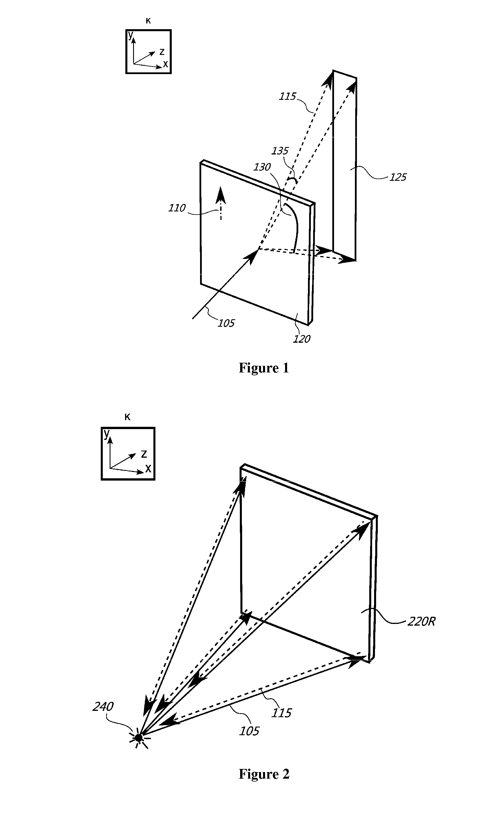
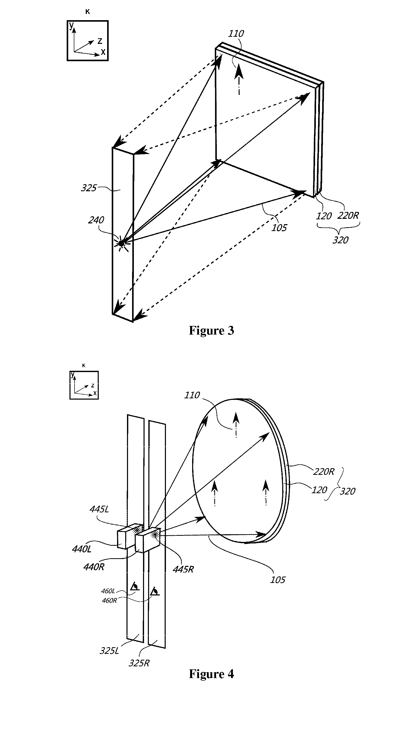
[0028]In order to understand the present invention, one must know how an exit pupil (325), so called viewing slit (325), is formed by a transfer screen (320), and what properties it has. Thus, in this section, the formation of viewing slits by the transfer screen (320) will be explained. In the next section, the present invention will be explained according to a preferred embodiment.

[0029]Autostereoscopic displays control light path such that they create viewing slits (325), through which different perspectives of the stereo image are observed, in different spatial ...


PUM


Abstract

The present invention is in the field of auto-stereoscopic displays. Two projectors are placed apart from each other and project a stereo image pair onto a transfer screen. The transfer screen forms two viewing slits. A head-tracker unit locates the position of viewer's eyes, a mechanical unit rotates the transfer screen around its center, according to the position information of viewer's eyes, such that right and left eye viewing slits are also rotated and formed on the right and left eye of the viewer, respectively. Thus, viewing slits dynamically track the viewer.

Description

TECHNICAL FIELD OF THE INVENTION[0001]The present invention is in the field of autostereoscopic displays. It relates to a method of creating dynamic exit pupils according to the viewer's position, and presenting the stereo images to the viewer.BACKGROUND OF THE INVENTION[0002]Autostereoscopic displays create virtual viewing windows, through which intended perspective images can be presented. Through these viewing windows, right and left eye of the viewer see different images, and perceive stereo image without the need of glasses. There are several different methods to create virtual viewing windows. These methods utilize parallax barrier, lenticular lenslet, Fresnel lens (pupil forming screen), retro-reflective light diffusing material, or light shaping diffuser (LSD) technology.[0003]In parallax barrier based displays, right and left eye images are interlaced in columns on the display, typically an LCD display. A parallax barrier is positioned in front of the display so that it cre...

Claims


Application Information

Patent Timeline
IPC IPC(8): H04N13/04G02B27/00H04N9/31G02B30/33H04N13/363
CPCH04N13/0413H04N13/0459G02B27/0081H04N9/3147H04N13/0468G02B5/0257H04N13/378H04N13/376H04N13/315H04N13/366H04N13/363G02B30/33G02B30/27
Inventor ELDES, OSMAN
Owner KOC UNIVSI
Learn More