
Low profile standalone cervical interbody with screw locking clips and method of using same

a technology of screw locking and screw, which is applied in the field of low-profile standalone cervical interbody with screw locking clips and method of using same, can solve the problems of difficult visual observation and difficult visual confirmation of the proper positioning of the backout/screw/cag

Inactive Publication Date: 2016-06-02
ALLIANCE PARTNERS
View PDF66 Cites 8 Cited by
  • Summary
  • Abstract
  • Description
  • Claims
  • Application Information

AI Technical Summary

Benefits of technology

The purpose of the resilient member in the clip is to ensure that it is in a position that prevents the screw from coming out. This prevents the screw from coming out while still being securely positioned. The resilient member can move into the interference position to prevent this from happening.

Problems solved by technology

When the screws are properly positioned and engaging a backout prevention member, the screw heads and much of the screws may be within the cage body and thus hard to visually observe.
The relative positions of the screw and the cage body often make difficult a visual confirmation the backout / screw / cage is properly positioned.

Method used


Image

  • Low profile standalone cervical interbody with screw locking clips and method of using same
  • Low profile standalone cervical interbody with screw locking clips and method of using same
  • Low profile standalone cervical interbody with screw locking clips and method of using same

Examples


Embodiment Construction

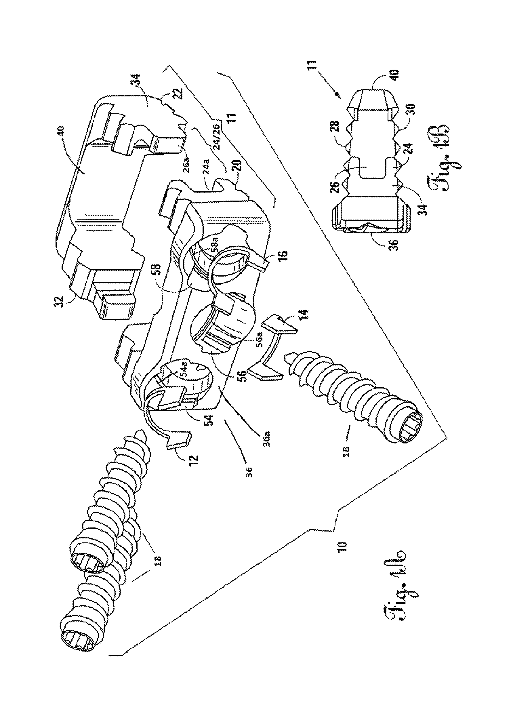
[0072]FIG. 1A illustrates the three main components of the interbody assembly 10 of the present invention. Cage 11 functions, in part, to maintain separation between a vertebra above and a vertebra below the interbody assembly. Screws 18 (a total of three as shown in the embodiment illustrated in FIG. 1A) provide fixation or location and stability of the cage to the vertebrae above and the vertebrae below the cage. Resilient clips 12 / 14 / 16, in the embodiment illustrated in FIG. 1A, engage both the cage 11 and the top of the screws 18 when the screw 18 is fully inserted into the cage 11 in a manner that prevents the screw 18 from, in time, backing out. Cages, clips, and screws generally are known in the art.

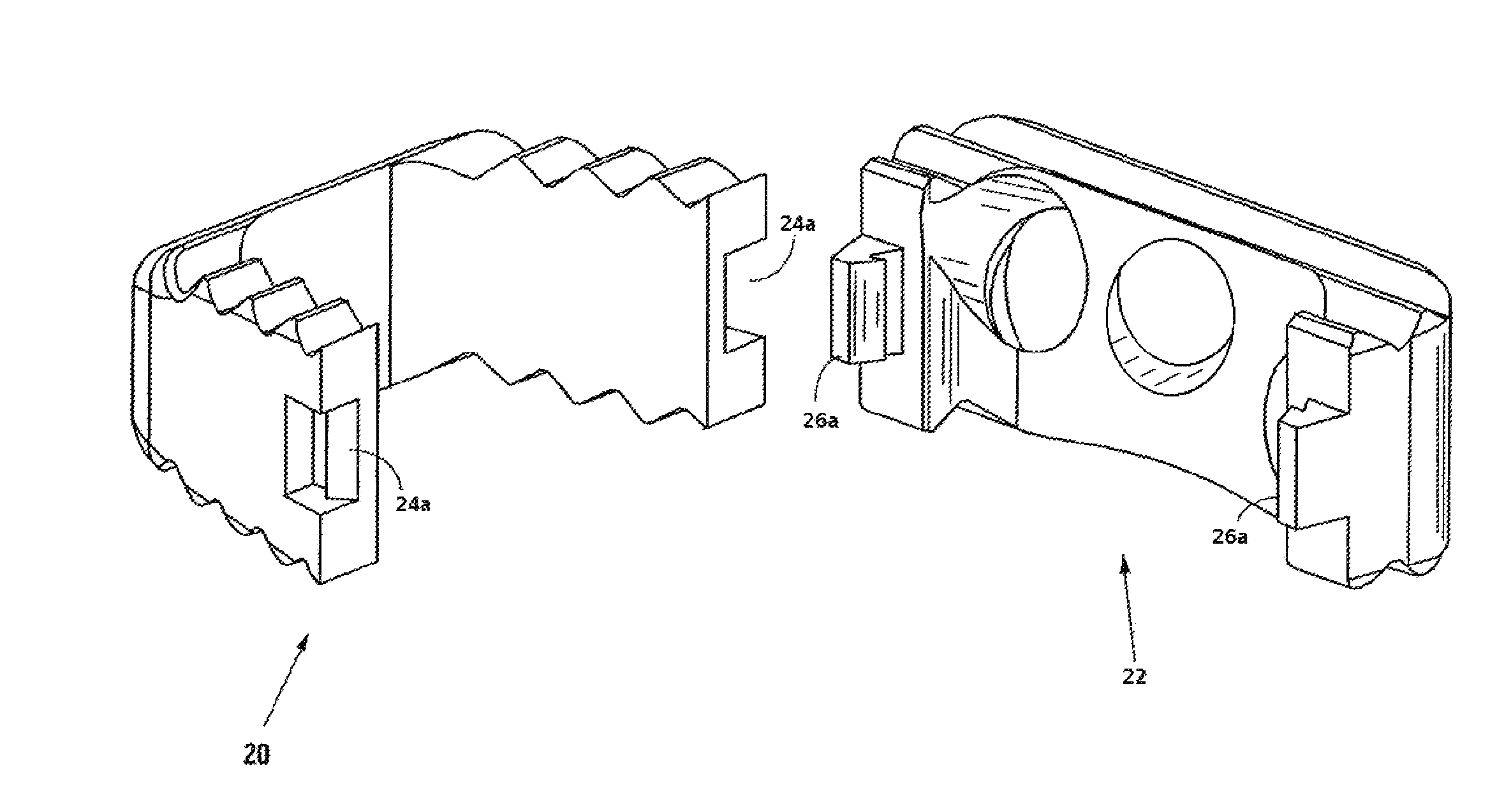
[0073]As seen in FIGS. 1A-5, the cage 11 of the present invention, in one embodiment, may include a first, anterior portion 20 and a second posterior portion 22. Engagement members 24 / 26 provide for engagement, such as tool-less resilient engagement, of a notched resilient arm 26a...


PUM


Abstract

A vertebrae stabilization device for stabilizing adjacent vertebrae that is a cage having screw locking clips and method of using same.

Description

CROSS-REFERENCE TO RELATED PATENT APPLICATIONS[0001]This application is a utility application claiming priority to U.S. Provisional Application Ser. No. 62 / 019,662, filed on Jul. 1, 2014, entitled “LOW PROFILE STANDALONE CERVICAL INTERBODY WITH SCREW LOCKING CLIPS,” which provisional patent application is commonly assigned to the Assignee of the present invention and is hereby incorporated herein by reference in its entirety for all purposes.FIELD OF THE INVENTION[0002]Screw anchored integrated vertebral standalone cage assemblies having screw anti-backout clips.BACKGROUND OF THE INVENTION[0003]In an effort to stabilize adjacent vertebrae when disks must be removed, a standalone interbody typically comprising a cage and screws may be used. The term standalone means that the cage is used without supplemental fixation, such as plates.[0004]Screws are used which engage the cage of an interbody assembly, which screws typically tap into the vertebrae bodies above and below the cage for m...

Claims


Application Information

Patent Timeline
Patent Type & Authority Applications(United States)
IPC IPC(8): A61F2/44
CPCA61F2220/0016A61F2/442A61F2/4455A61F2/447A61F2002/30131A61F2002/30481A61F2002/305A61F2002/30604A61F2002/30787A61F2002/30904
Inventor MORRIS, FRANKLEWIS, DWAYNERICHARDSON, KEVIN
Owner ALLIANCE PARTNERS
Learn More