
Levelling Device

a technology for levelling devices and wall plates, applied in measurement devices, instruments, surveying and navigation, etc., can solve problems such as unsatisfactory appearance and unstraight edges of wall plates

Inactive Publication Date: 2016-05-26
LAMONT LUKE +1
View PDF13 Cites 4 Cited by
  • Summary
  • Abstract
  • Description
  • Claims
  • Application Information

AI Technical Summary

Benefits of technology

The present invention is a device for leveling wall mounted plates, such as power sockets and light switches. The device includes a body with level indicators, electrical socket pins, studs, and openings for a screwdriver. The device also includes a cross member and ribs for added strength. The device can be used to securely tighten screws on a wall plate. The technical effects of the invention include improved accuracy in leveling and secure mounting of wall plates.

Problems solved by technology

However, some wall plates do not have straight edges against which the level can be held.
Also, in many situations an installer may simply set the orientation of the plate by eye due to the inconvenience of using a conventional spirit level.
Any resulting tilt in the wall mounted plate results in an unsatisfactory appearance.

Method used


Image

  • Levelling Device
  • Levelling Device
  • Levelling Device

Examples


first embodiment

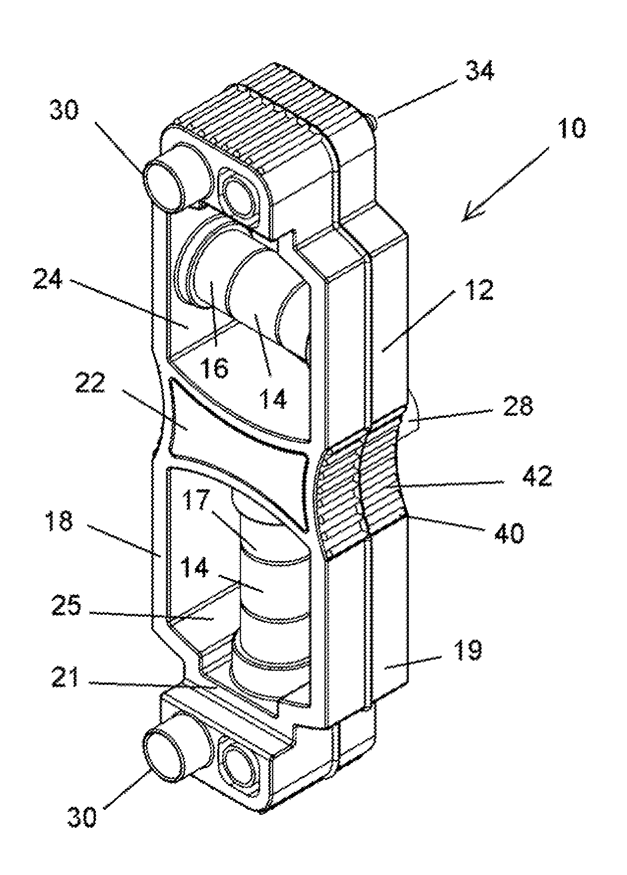
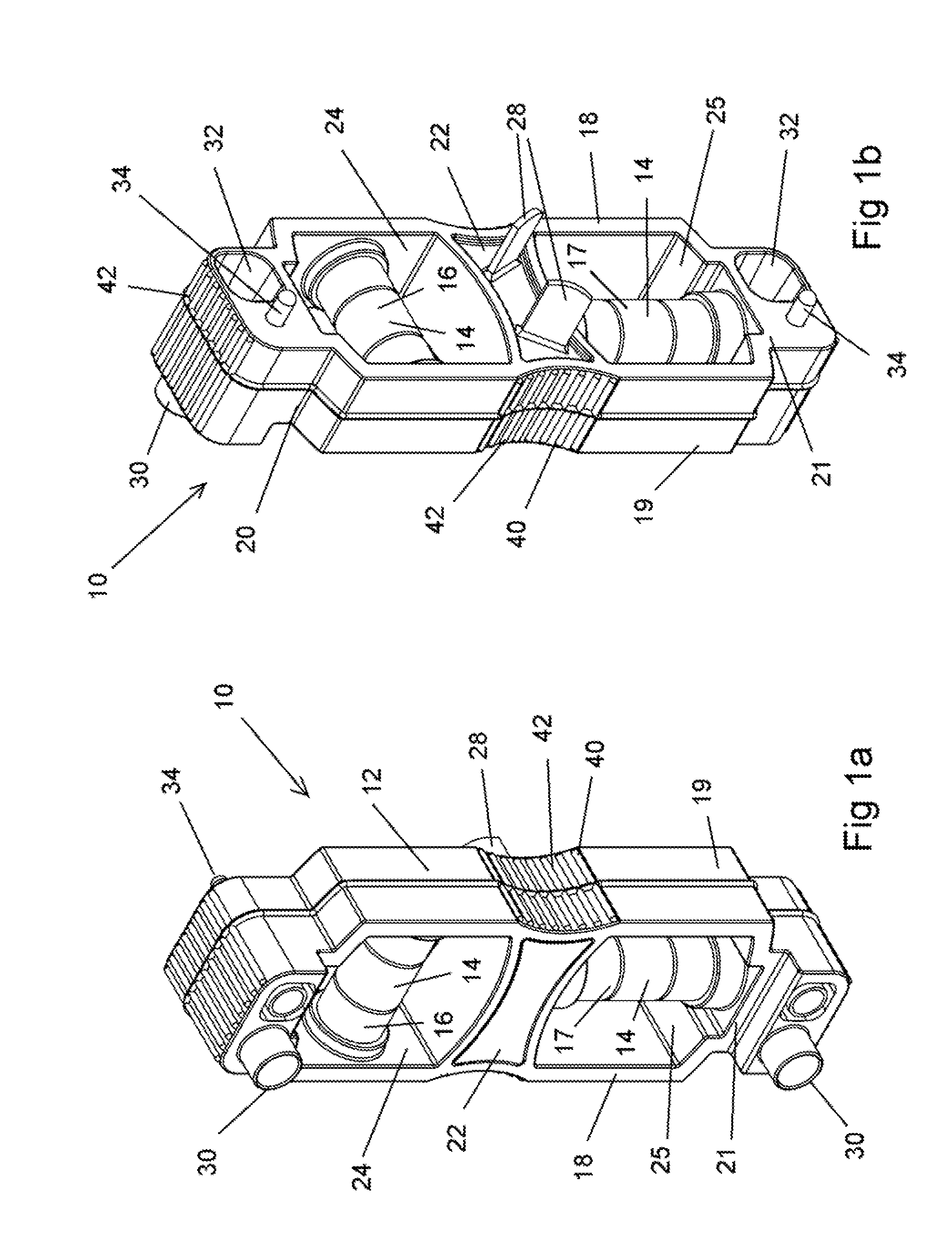
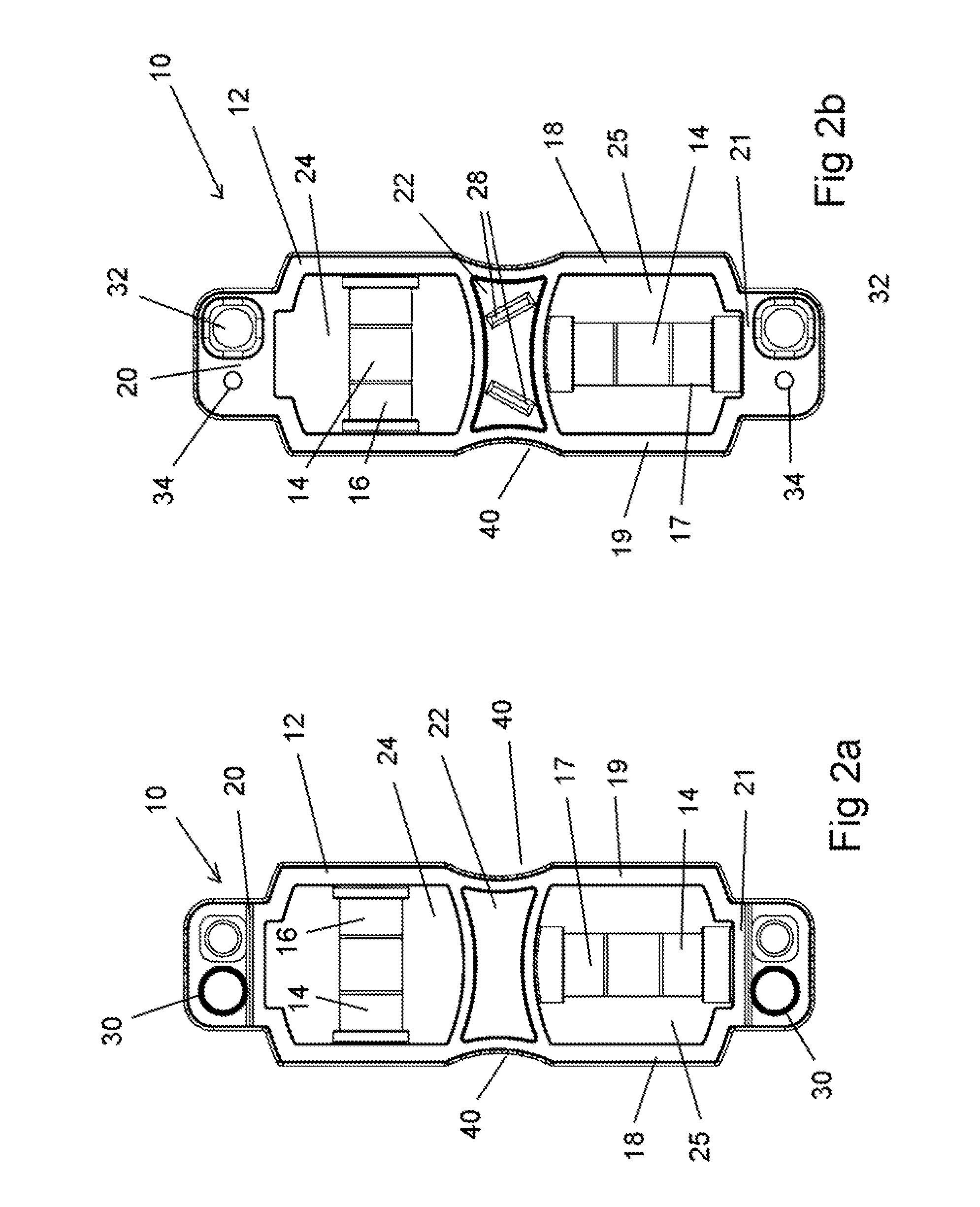
[0083]Referring to FIGS. 1 to 9, there is shown a levelling device 10 in accordance with the present invention. The levelling device comprises a body portion 12 having one or more level indicators 14 mounted therein. In the embodiment shown, there is provided a first level indicator 16 and a second level indicator 17. Each of the first and second level indicators 16 and 17 comprise a spirit level tube. The first and second spirit level tubes are arranged perpendicular to each other to provide an indication of whether the body portion 12 is level in either the horizontal or vertical orientation.

[0084]In the embodiment shown, the body portion 12 comprises first and second parallel side members 18 and 19 and first and second end members 20 and 21. The first end member 20 joins the first and second side members 18 and 19 adjacent first ends thereof and the second end member 21 joins the first and second side members 18 and 19 adjacent second ends thereof. There is also provided a centra...

second embodiment

[0097]FIGS. 10 to 20 show a levelling device 10 in accordance with the present invention. The levelling device 10 of FIGS. 10 to 20 is similar to the embodiment of FIGS. 1 to 9 and like reference numerals are used to denote like parts.

[0098]The levelling device comprises also a body 12 formed of first and second side members 18 and 19 and first and second end members 20 and 21. First and second level indicators 16 and 17 are mounted within the body 12.

[0099]The electrical socket pins 28 comprise straight flat pins of a shape to be received in electrical sockets of the type used in the USA. The electrical socket pins 28 extend outwardly from a side surface of the first side member 18 of the body 12, generally midway the first and second end members 20 and 21. The first studs 34 also extend outwardly from the side surface of the first side member 18, adjacent opposed ends thereof. The first studs 34 are spring biased in the same manner as the first embodiment such that the first studs...


PUM


Abstract

Described is a levelling device (10) comprising a body portion (12) having one or more level indicators (14) mourned therein and a pair of electrical socket pins (28) extending outwardly from a first side of the body portion (12) arranged to be received in apertures (29) provided in a power socket of a wall plate (26).

Description

CROSS-REFERENCE TO RELATED APPLICATIONS[0001]This is a Continuation-in-Part Application of U.S. Non-Provisional Patent Application No. 14 / 358,040 filed May 14, 2014, entitled, “Levelling Device,” which is the National Stage of International Application No. PCT / AU2012 / 001396, filed Nov. 13, 2012.BACKGROUND OF THE INVENTION[0002](1) Field of Invention[0003]The present invention relates to a device for levelling wall mounted plates and, more particularly, to a device for levelling wall mounted plates, including power sockets and light switches.[0004](2) Description of Related Art[0005]A Variety of all mounted plates are used for different purposes in buildings. Electrical equipment, for example, commonly uses wall mounted plates, such as light switches and power sockets. These plates are affixed to the wall using conventional means, such as screws received through apertures in the plate.[0006]It is desirable with such wall mounted plates to ensure that the edges of the plates are orien...

Claims


Application Information

Patent Timeline
Patent Type & Authority Applications(United States)
IPC IPC(8): G01C9/28G01C9/34
CPCG01C9/34G01C9/28H02G2200/30
Inventor LAMONT, LUKEKHOURY, EDWARD JOSEPH
Owner LAMONT LUKE
Learn More