
Wire harness

a wire harness and wire technology, applied in the direction of insulated conductors, cables, conductors, etc., can solve problems such as cable disconnection

Active Publication Date: 2016-04-21
SUBARU CORP
View PDF4 Cites 5 Cited by
  • Summary
  • Abstract
  • Description
  • Claims
  • Application Information

AI Technical Summary

Benefits of technology

The purpose of this patent is to create a wire harness that can find twist without damaging the appearance of the harness.

Problems solved by technology

When a wire harness that bundles cables is attached to a vehicle as twisted, the cable undergoes excessive tensional force of the twist, which can cause cable disconnection.

Method used


Image

  • Wire harness
  • Wire harness
  • Wire harness

Examples


Embodiment Construction

[0025]Hereinafter, preferred implementations of the present disclosure will be described in detail with reference to the appended drawings. Dimensions, material, and other specific numerical values mentioned in the implementations are merely examples for facilitating understanding of the present disclosure, and do not limit the present disclosure if not stated otherwise. Note that, in this specification and the appended drawings, structural elements that have substantially the same function and structure are denoted with the same reference numerals, and repeated explanation of these structural elements is omitted. Elements not directly related to the present disclosure are not illustrated in the drawings.

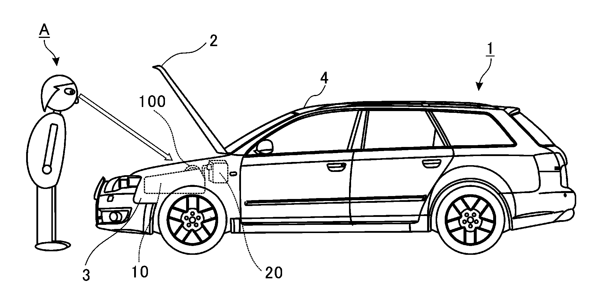
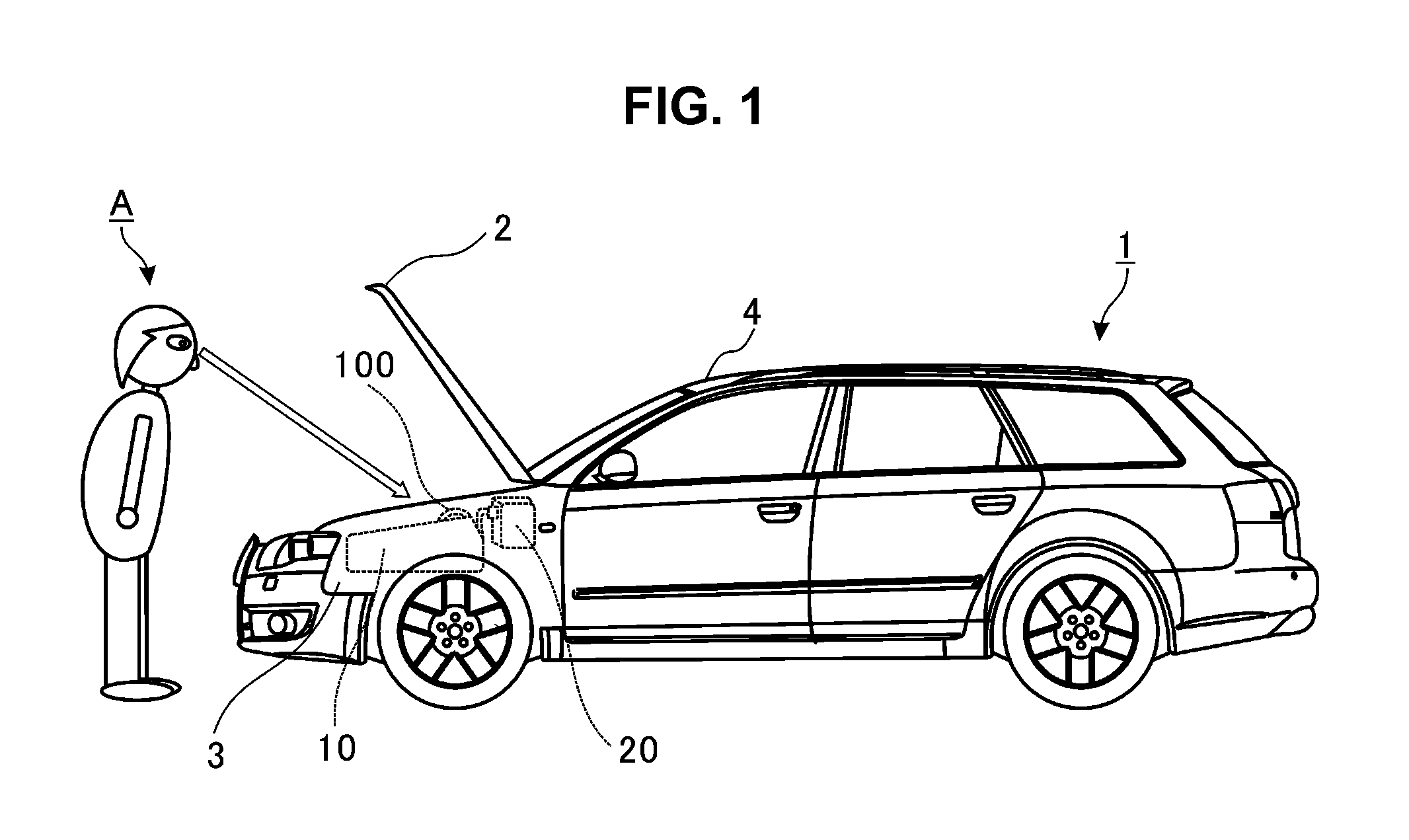
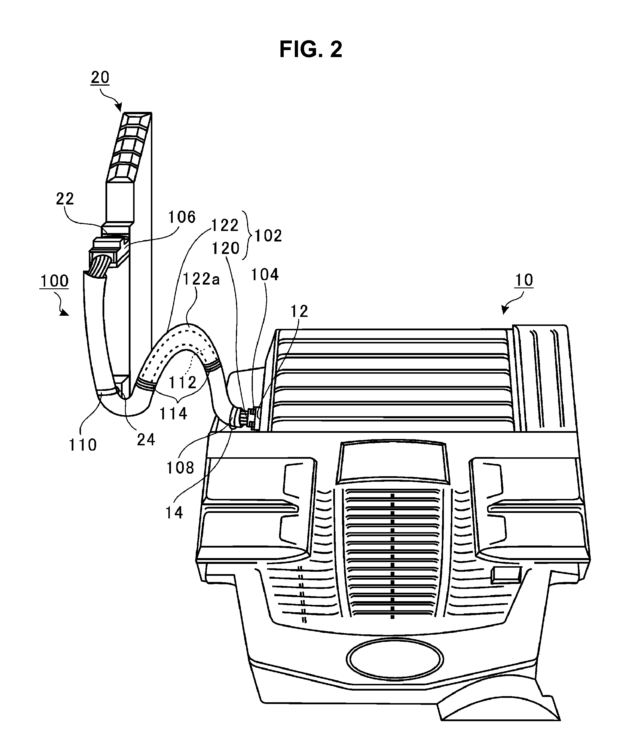
[0026]FIG. 1 is a side view of a vehicle 1. The advancing direction of the vehicle 1 and the reversing direction of the vehicle 1 will be respectively referred to as front side (left side in FIG. 1) and rear side (right side in FIG. 1). As illustrated in FIG. 1, the vehicle 1 includ...


PUM

PropertyMeasurementUnit
circumferenceaaaaaaaaaa
areaaaaaaaaaaa
areasaaaaaaaaaa

Abstract

A wire harness includes a cable unit, and an indicator provided that is on a back surface portion of an outer circumference surface of the cable unit, the back surface portion being positioned on an opposite side to a front surface portion that is visually recognizable from a direction in which the wire harness is visually recognizable to a worker in a normal attachment state in which the cable unit is attached to a vehicle in a predefined attachment manner.

Description

CROSS-REFERENCE TO RELATED APPLICATIONS[0001]The present application claims priority from Japanese Patent Application No. 2014-211925 filed on Oct. 16, 2014, the entire contents of which are hereby incorporated by reference.BACKGROUND[0002]1. Technical Field[0003]The present disclosure relates to a wire harness to be attached to a vehicle.[0004]2. Related Art[0005]When a wire harness that bundles cables is attached to a vehicle as twisted, the cable undergoes excessive tensional force of the twist, which can cause cable disconnection. Thus, such twist conventionally needs finding.[0006]Various technologies have been disclosed for finding twist of a wire harness. For example, it is proposed to provide a tape to the outer circumference surface of a sheathing layer that sheathes bundled cables along the longitudinal direction of the cables, the tape having a different color from the color of the sheathing layer (for example, Japanese Unexamined Utility Model (Registration) Application ...

Claims


Application Information

Patent Timeline
Patent Type & Authority Applications(United States)
IPC IPC(8): B60R16/02H01B7/40H01B7/36
CPCB60R16/0215H01B7/40H01B7/36H01B7/368H02G3/0406H02G2200/20H02G3/0481H02G3/32
Inventor KASUYA, YUJIMATSUMOTO, NOBORU
Owner SUBARU CORP
Learn More