
Transmission terminal, transmission system, display method and program

a technology of transmission system and transmission terminal, applied in the field of transmission terminal, can solve problems such as not always easy to determin

Inactive Publication Date: 2016-04-14
RICOH KK
View PDF6 Cites 21 Cited by
  • Summary
  • Abstract
  • Description
  • Claims
  • Application Information

AI Technical Summary

Benefits of technology

The present invention is about a video conference system that allows users to change the names displayed on the screens of other conference participants. This solves a problem that existed in previous video conference systems where users could not easily change the names of the devices they were using during the conference.

Problems solved by technology

However, for a user of the terminal device, it is not always easy to determine from which terminal device the image data displayed on the display unit are sent out from other parties in the video conference.

Method used


Image

  • Transmission terminal, transmission system, display method and program
  • Transmission terminal, transmission system, display method and program
  • Transmission terminal, transmission system, display method and program

Examples


first embodiment

[0044]Although the present invention has been described with reference to embodiments, the present invention is not limited to these embodiments, but various variations and modifications may be made without departing from the scope of the invention as set forth in the accompanying claims.

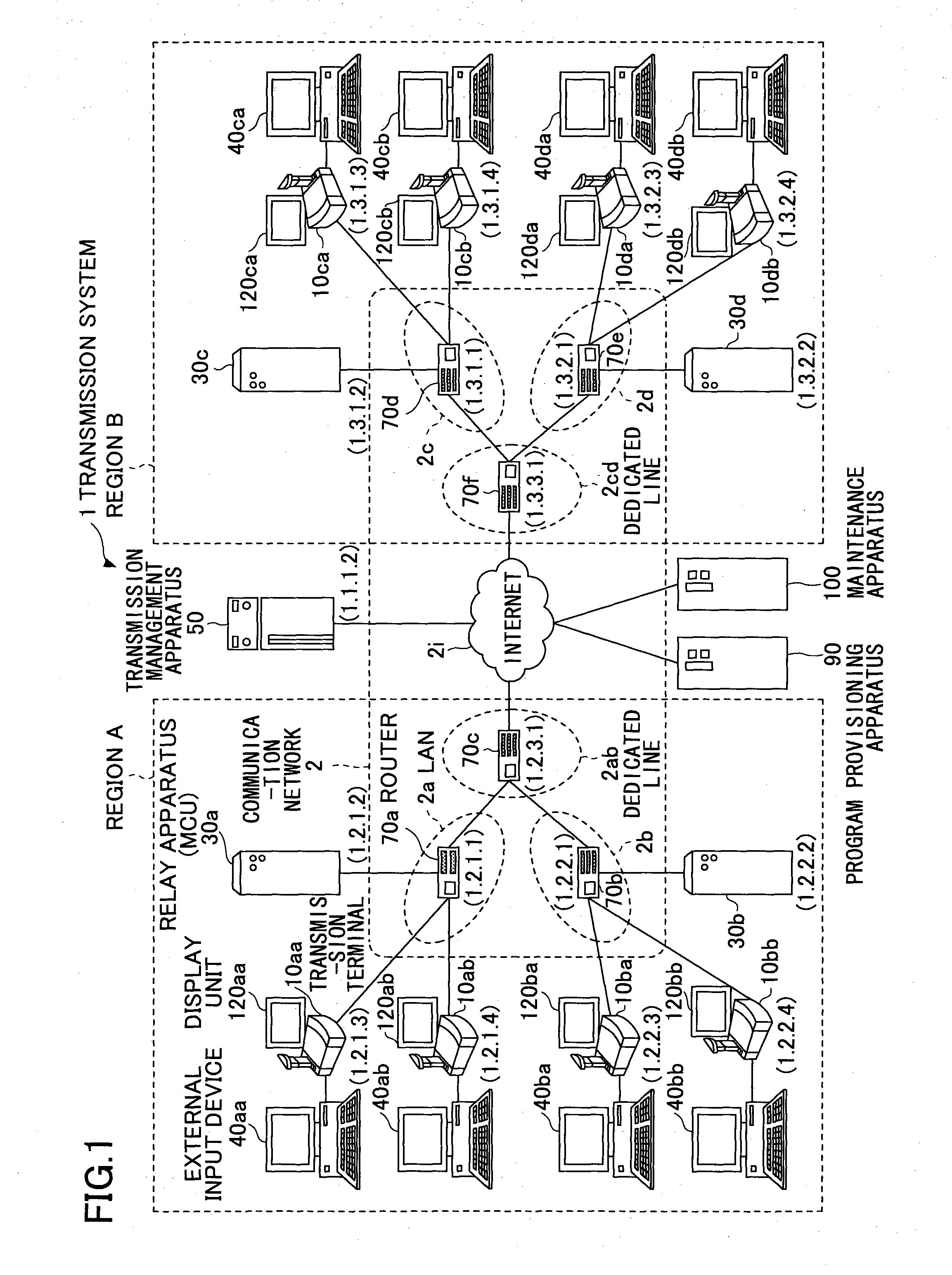
[0045]FIG. 1 is a diagram schematically illustrating a whole configuration of a transmission system 1 according to a present embodiment. In the following, with reference to FIG. 1, the transmission system 1 according to the present embodiment will be explained.

[0046]In general, a transmission system includes a data provisioning system in which content data are unidirectionally transmitted from one transmission terminal to the other terminal via the transmission management apparatus, or a communication system in which information, emotion or the like is transmitted mutually among plural transmission terminals via the transmission management apparatus. This communication system is a system that transm...


PUM


Abstract

A transmission terminal is for a communications connection with an other terminal via a network. The transmission terminal includes a reception unit that receives display data to be displayed on a display unit connected to the transmission terminal from the other terminal; a name acquisition unit that acquires a name associated with the other terminal from one or more names that are registered for the transmission terminal in advance; a name overlaying unit that generates overlaid display data by incorporating the acquired name in the display data; and an image display control unit that displays the overlaid display data on the display unit.

Description

TECHNICAL FIELD[0001]The present invention relates to a transmission terminal or the like for a communications connection with an other terminal via a network.BACKGROUND ART[0002]Recently, a transmission system to conduct a video conference between remote locations via a communication network, such as the Internet, has become popular. In such a transmission system, by sending and receiving image data and voice data between plural transmission terminals, the video conference is realized. Moreover, according to recent enhancements of the broadband environment, high-quality image data and voice data can be sent and received, understanding the status of the other party in the video conference becomes easier, and the fulfillment of communication by a video conference has been improved.[0003]On a display unit of a terminal device, image data obtained by taking an image of the other party in the video conference are displayed. However, for a user of the terminal device, it is not always ea...

Claims


Application Information

Patent Timeline
Patent Type & Authority Applications(United States)
IPC IPC(8): H04N7/15H04N5/265H04M1/724
CPCH04N5/265H04N7/15H04M1/575H04M2250/62H04M1/724
Inventor NAGASE, TATSUYAKATO, YOSHINAGA
Owner RICOH KK
Learn More