Eureka AIR delivers breakthrough ideas for toughest innovation challenges, trusted by R&D personnel around the world.

Device for managing an accumulator

a technology for managing devices and accumulators, applied in secondary cell servicing/maintenance, cell components, batteries, etc., can solve problems such as accumulator thermal runaway, component melt, and deflagration of the cover, and achieve accurate knowledge of the state

Active Publication Date: 2016-03-10
COMMISSARIAT A LENERGIE ATOMIQUE ET AUX ENERGIES ALTERNATIVES
View PDF3 Cites 1 Cited by
  • Summary
  • Abstract
  • Description
  • Claims
  • Application Information

AI Technical Summary

Benefits of technology

The patent describes a calibrating method for a device that manages the use of a pack that includes an accumulator. The method involves measuring the state of the accumulator during charging and discharging, in order to prevent damage. Once the device is calibrated, it can be attached to the pack and used to manage its operation. The device also allows accurate assessment of the state of each accumulator in a pack with multiple accumulators. The technical effects include improved management of packs comprising accumulators and accurate monitoring of their state.

Problems solved by technology

Indeed, a lithium electrochemical cell comprises an organic electrolyte which, unlike an aqueous electrolyte, does not allow to consume, through the existence of a secondary reaction, an overcharge current appearing in the accumulator during a too long or abnormal charging cycle.
Too high an overcharge current can thus cause the deflagration of the cover which insulates the accumulator from its outside environment.
The electrical overcharge phenomena can also cause a thermal runaway of the accumulator that can cause these components and / or the protecting cover to melt.
As above, the accumulator aging can cause an explosion of the pack or a thermal runaway of the accumulator.
The electrochemical reaction can thus be unbalanced at the electrodes and cause thermal runaway of the accumulator.
This solution is extreme because on the one hand, it releases in the environment noxious chemical compounds which were desired to be confined in the cover and on the other hand the accumulator is no longer usable because the impermeability of the cover is irreversibly broken.
Another drawback related to this solution is the space occupied by the thermal fuse inside the pack.
In other words, the presence of one or more thermal fuses in a pack increases the risks of the pack failure and increases the cover volume to insulate the electrochemical cells from their outside environment.
As well as for the devices above, separating elements irreversibly degrade the pack when the same is in a safety state.
In other words, it is no longer possible to use the pack after triggering this safety device.
Hence, the overcharge of an accumulator cannot be detected from several accumulators operating normally.
On the other hand, the measurement of the electric voltage at the terminals of the pack can be unable to provide reliable information insofar as the electric voltage measured is not specific to a value of the state of charge.
This results in complexifying the balancing of the inter-element state of charge, based on the measurement of the voltage difference between each element.
Furthermore, the operating conditions of the pack (value of the electrical current at the terminals of the pack, internal temperature) can modify the pack behaviour and thus disturb interpretation of the measurements.

Method used


Image

  • Device for managing an accumulator
  • Device for managing an accumulator
  • Device for managing an accumulator

Examples


Embodiment Construction

[0063]The invention relates to a managing device for monitoring the state of charge and safety (with the meaning already defined above) of a pack comprising a lithium accumulator, and enabling the state of aging of said pack to be known in real time. An exemplary embodiment of a managing device is described in a first part of the present disclosure. In a second part, an exemplary method for calibrating and using the managing device, enabling a pack to be optimally used is described. These two exemplary embodiments are completed with several alternatives or variants which can be combined together to form new embodiments.

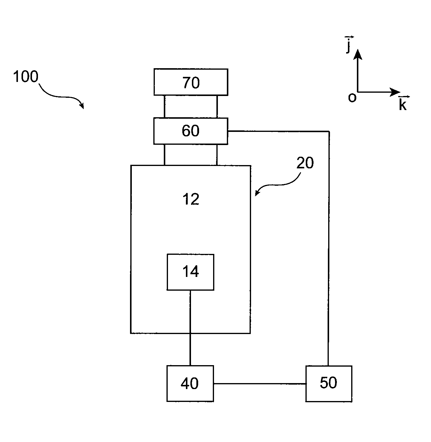
[0064]The first part of the detailed disclosure thus relates to an exemplary managing device enabling the state of charge or safety, as well as the state of health, of a pack 20 comprising a single lithium accumulator, to be followed up in real time. In order to aid the reader in understanding the invention, the managing device 100 is represented attached to the pack ...


PUM

PropertyMeasurementUnit
operating temperatureaaaaaaaaaa
temperatureaaaaaaaaaa

Abstract

A device for managing an accumulator, including: a plurality of strain gauges including at least three strain gauges, the strain gauges being arranged to measure stresses along at least three distinct stress axes; a measuring device measuring strains undergone by each gauge along its stress axis; a reversible electrical switch; a calculating device controlling opening and closing of the electrical switch, depending on measurements carried out by the measuring device.

Description

TECHNICAL FIELD[0001]The present application belongs to the technical field of electrochemical generators. The invention more particularly relates to a device and a method for using the same, enabling an accumulator to be monitored and followed up during the use thereof. In other words, the invention is directed to the technical field associated with the management of the operation of an electrochemical accumulator.STATE OF PRIOR ART[0002]Within the scope of the present application, the term accumulator designates an electrochemical cell comprised of a positive electrode and a negative electrode, separated by a separator, the whole being in contact with an electrolyte.[0003]The accumulator is insulated from the outside environment by a cover which can be open, partially impermeable or perfectly impermeable depending on the technology considered and the electrochemical mechanisms implemented. The materials and additives, some of which can be pollutant or toxic, are thus contained in ...

Claims


Application Information

Patent Timeline
Patent Type & Authority Applications(United States)
IPC IPC(8): H01M10/48H01M10/42
CPCH01M10/48H01M2010/4271H01M10/425H01M10/052H01M10/482H01M2200/20Y02E60/10H01M50/578
Inventor GENIES, SYLVIEALIAS, MELANIECOUTIER, CAROLINELE BARON, ESTELLEMAILLEY, SOPHIE
Owner COMMISSARIAT A LENERGIE ATOMIQUE ET AUX ENERGIES ALTERNATIVES
Why Eureka
Eureka Blog
Learn More