
Mount for decorative element

Inactive Publication Date: 2016-02-18
MCCASLIN LARRY G +1
View PDF1 Cites 12 Cited by
  • Summary
  • Abstract
  • Description
  • Claims
  • Application Information

AI Technical Summary

Benefits of technology

The invention is a mount for a decorative element that can be easily replaced without needing to move or replace the base. The mount includes a bucket that can be positioned either under the base or in a hole through the base, and a ring located above the base. The bucket and ring have structure for engaging the base to mount the decorative element without accessing the underneath. The mount includes means for either advancing the bucket or ring towards each other to securely mount the decorative element to the base. The ring also has a space for storing the decorative element when it is mounted.

Problems solved by technology

Generally comprised of brass, bronze, or other semi-valuable material, and therefore heavy and expensive, the vase holds flowers and / or other displays provided by the family of the deceased or by the operator of the cemetery.
Unfortunately, because they are comprised of bronze, these vases are often a target for thieves; for some reason, they are also a favorite target for graveyard vandals.
After it is stolen or damaged, the vase must be replaced, and it is not uncommon for several vases to be stolen or damaged at the same time such that replacing the vases requires substantial resources.
The logistics of replacing stolen or damaged ceremonial vases are made more difficult by the relatively large and heavy nature of the vases, making them difficult to transport, handle, and store.
Another problem that must be addressed is the actual replacement of the vase or other decorative element that is mounted to or on a grave marker because the mount, and sometimes even the grave marker itself, may be damaged when the vase or decorative element is vandalized or stolen.

Method used


Image

  • Mount for decorative element
  • Mount for decorative element
  • Mount for decorative element

Examples


Embodiment Construction

)

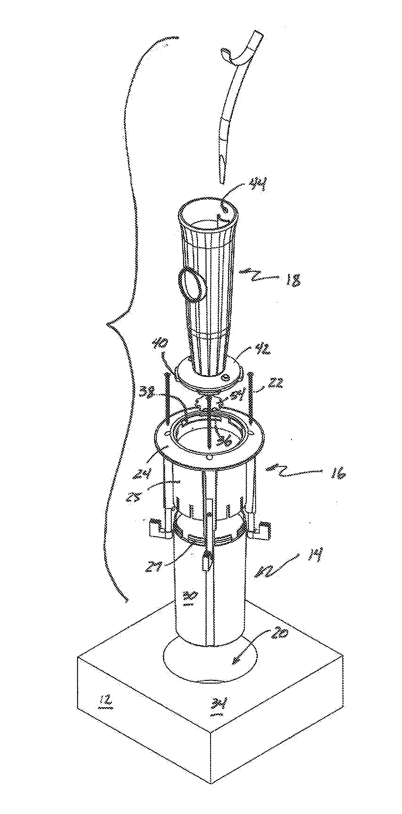
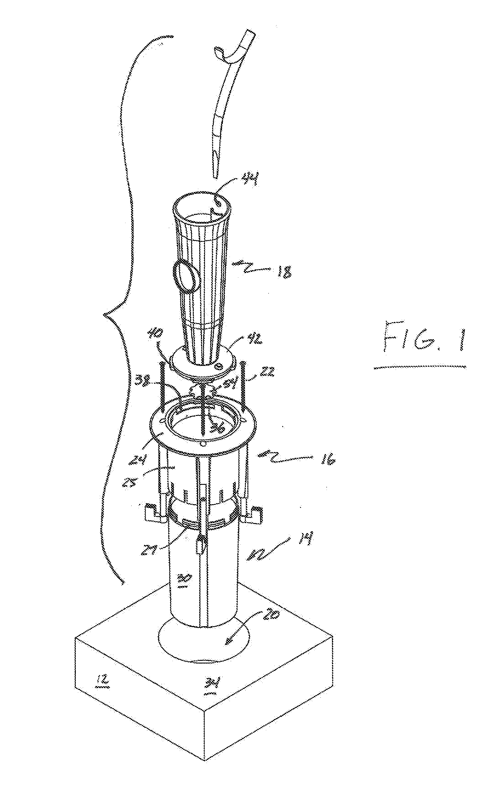
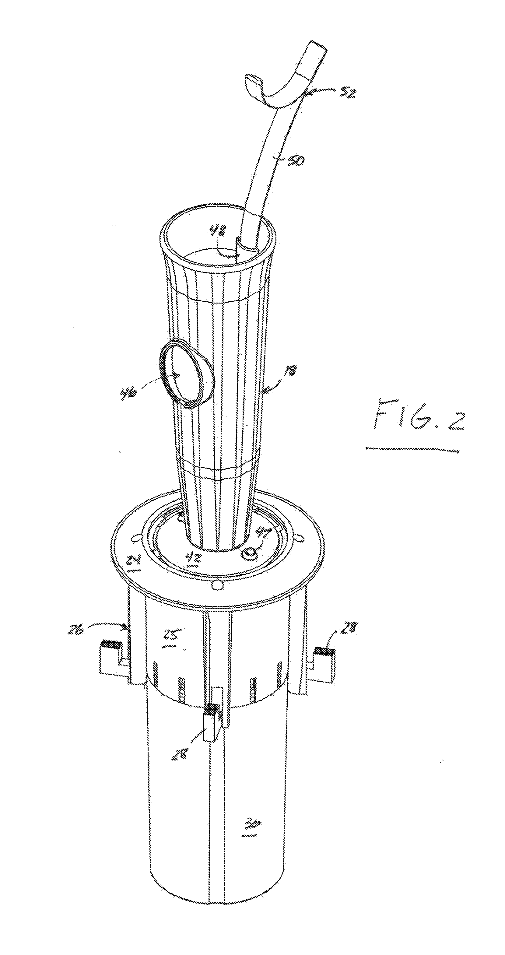
[0015]Referring to the figures, one embodiment of a mount for a decorative element for a grave marker that is constructed in accordance with the present invention is indicated generally at reference numeral 10. The particular embodiment shown is intended to be affixed to a base that may take the form of a horizontal grave marker, headstone, memorial, or other element, a portion of which is shown at reference numeral 12 in FIGS. 1, 3, and 4, but as described in more detail below, those skilled in the art will recognize from this disclosure that the mount of the present invention also enables the mounting of a decorative element to bases that are not horizontal. Those skilled in the art will also recognize from this description that the surface to which the mount of the present invention is affixed need not be a grave marker or headstone, hence the use of terms such as “base” and “structural element” in this specification to describe the structure to which the mount for a decorative ...


PUM


Abstract

A mount for a decorative element for a grave marker, headstone, or other structure for displaying flowers or other indicia provided by the family and / or cemetery operator. The mount is affixed to the marker by inserting a bucket into a hole in the base, mounting a ring to the bucket, and activating structure formed on the bucket to draw that structure into engagement with the undersurface of the base. Once the ring and bucket are affixed to the base, a decorative element is releasably secured to the ring. Either or both of the decorative element or ring is provided with a receptacle for receiving a flag pole, a scabbard for receiving the lance of a wreath holder, or a landing for receiving an insert marked with commemorative or display indicia.

Description

[0001]This application claims the benefit of U.S. provisional application No. 61 / 866,655, filed Aug. 16, 2013. Application No. 61 / 866,655 is hereby incorporated into this application in its entirety by this specific reference thereto.BACKGROUND OF THE INVENTION [0002]The present invention relates to a mount for a decorative element such as a vase or urn that is mounted to a grave, headstone, or other ceremonial marker or memorial. In more detail, the present invention relates to a mount for a decorative element that, in one embodiment, is as an urn or vase for mounting to a grave, headstone, or other indoor or outdoor wall, mausoleum, columbarium, memorial, historical or commemorative site, or other ceremonial marker.[0003]A visit to any cemetery will reveal that a large number of grave markers are provided with a ceremonial urn or vase. Generally comprised of brass, bronze, or other semi-valuable material, and therefore heavy and expensive, the vase holds flowers and / or other displ...

Claims


Application Information

Patent Timeline
IPC IPC(8): E04H13/00A01G9/02A47G7/04A47G7/06F21V33/00
CPCE04H13/001A01G9/02A47G7/06F21W2121/00E04H13/003F21V33/0028A47G7/041
Inventor MCCASLIN, LARRY G.MCCASLIN, MARK A.
Owner MCCASLIN LARRY G
Learn More