Control device, head-mount display device, program, and control method for detecting head motion of a user
a control device and display device technology, applied in the direction of static indicating devices, selective content distribution, instruments, etc., can solve the problems of unintended operation, large circuit size, high cost, etc., and achieve the effect of recognizing more quickly and more accurately the operation
- Summary
- Abstract
- Description
- Claims
- Application Information
AI Technical Summary
Benefits of technology
Problems solved by technology
Method used
Image
Examples
first embodiment
[0045]A head-mount display device (hereinafter, briefly referred to as HMD) 101 of the present embodiment identifies different kinds of processing instructed by user's motions in the same direction, on the basis of the amplitude of the head motion, while preventing execution of unintended processing caused by a return motion of the user's head.
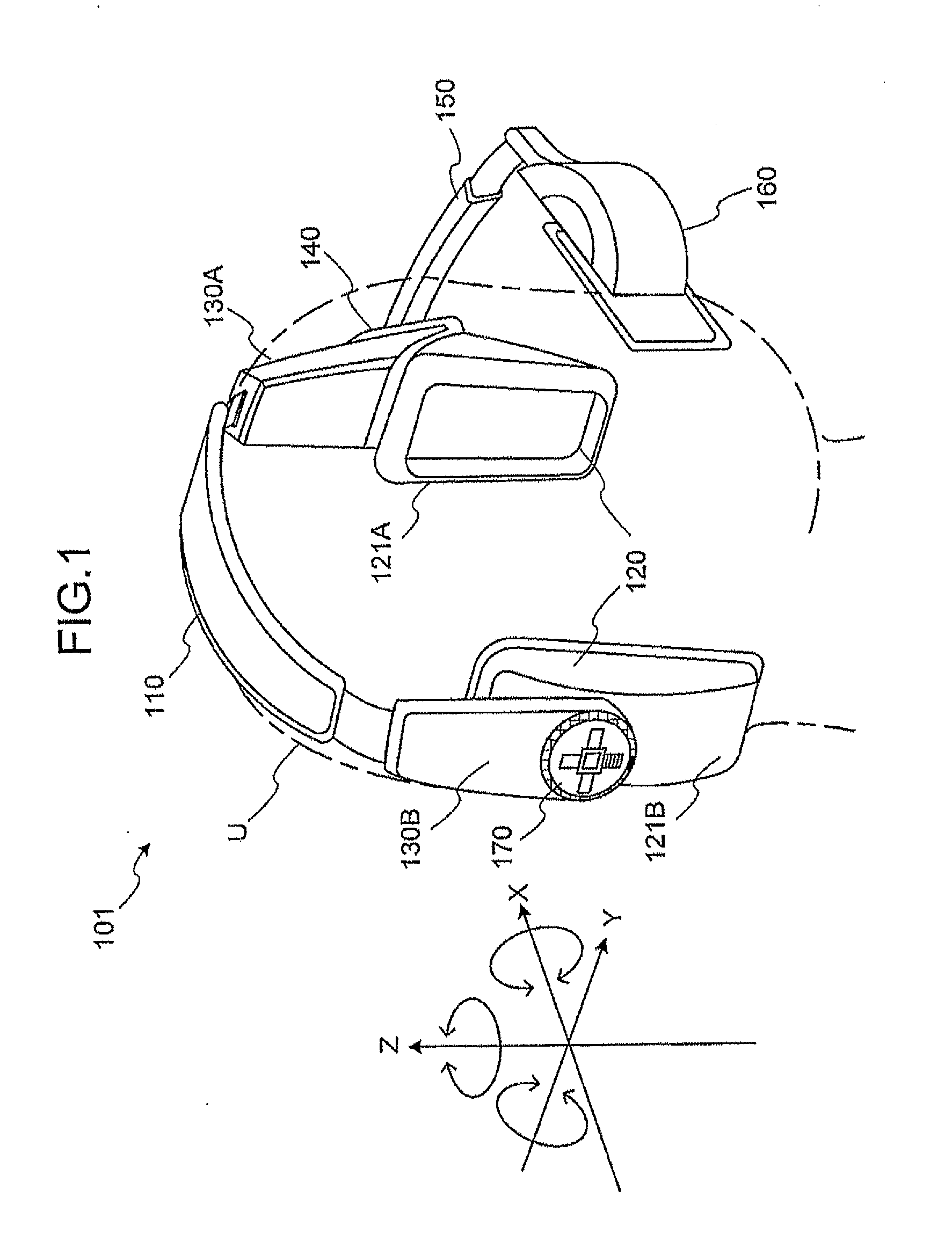
[0046]FIGS. 1 and 2 show the head mount display device 101. FIG. 1 is a perspective view showing the HMD 101 of the first embodiment of the present invention, and FIG. 2 is a side view showing the HMD 101 of the first embodiment.
[0047]As shown in the figures, the HMD 101 of the present embodiment comprises a head-mounting band 110, a sound output unit 120, housings 130A and 130B, a supporting unit 140, an arm unit 150, a display unit 160, and an operation unit 170.
[0048]The head-mounting band 110 is formed into a curved shape such that both ends face each other. Further, the head-mounting band 110 is made of elastic material, so that speakers ...
second embodiment
[0134]Next, a second embodiment of the present invention will be described. In the following, an HMD 102 as the second embodiment will be described with respect to different points from the first embodiment.
[0135]The HMD 102 of the second embodiment of the present invention differs from the first embodiment in that the HMD 102 displays an indicator expressing angular velocities visually. FIG. 11 is a block diagram showing a functional configuration of the HMD 102.
[0136]A control unit 410 will be described. The control unit 410 comprises a motion analysis unit 411, a time measuring unit 412, a signal control unit 413, and a display bar generation unit 414.
[0137]The control unit 410 displays an indicator 800 of a cross shape as shown in FIG. 13 on a screen of a display device provided in a display unit 160.
[0138]The indicator 800 is of a cross shape having angular velocity display areas 810A, 810B, 810C and 810D (simply expressed as angular velocity display area 810 when it is not nec...
third embodiment
[0163]Next, a third embodiment of the present invention will be described. An HMD 103 of the present embodiment is also similar to the HMD 101 of the first embodiment, and thus description of the same components will be omitted.
[0164]The HMD 103 of the third embodiment of the present invention differs from the HMD of the first embodiment in that corrected coordinates are calculated from the coordinate system for detection by angular velocity sensors and a user's coordinate system.
[0165]When the HMD 103 is mounted on the user's head, screen operation concerning the display screen of the display unit 160 can be performed basically when the user moves his head. However, sometimes error occurs owing to user's way of mounting the HMD 103 on his head, user's way of moving his neck out of habit, or the like, and the user cannot always perform intended operation.
[0166]Thus, in order to perform accurate operation by user's own head motion, the HMD 103 of the present embodiment performs proce...
PUM
 Abstract
Description
Claims
Application Information
 - R&D
- Intellectual Property
- Life Sciences
- Materials
- Tech Scout
- Unparalleled Data Quality
- Higher Quality Content
- 60% Fewer Hallucinations
Browse by: Latest US Patents, China's latest patents, Technical Efficacy Thesaurus, Application Domain, Technology Topic, Popular Technical Reports.
© 2025 PatSnap. All rights reserved.Legal|Privacy policy|Modern Slavery Act Transparency Statement|Sitemap|About US| Contact US: help@patsnap.com


