
Bra and bra components

Active Publication Date: 2015-11-26
REGINA MIRACLE INTERNATIONAL (GROUP) LIMITED
View PDF28 Cites 10 Cited by
  • Summary
  • Abstract
  • Description
  • Claims
  • Application Information

AI Technical Summary

Benefits of technology

The present invention provides an underwire casing for a bra that includes an electrically conductive fabric layer for contact with the wearer's body. The underwire casing may be a fabric casing for receiving an underwire and the electrically conductive fabric layer is wrapped around the fabric casing. The bra also includes a breast cup with an inner surface that is in contact with the wearer's body, and the lower edge region of the breast cup has an electrically conductive fabric layer for contact with the user's skin. The bra may also have an underwire positioned within the underwire casing of each breast cup. The technical effect of the invention is to provide a bra that can better support and comfort the wearer while also providing better electrical conductivity for the underwire.

Problems solved by technology

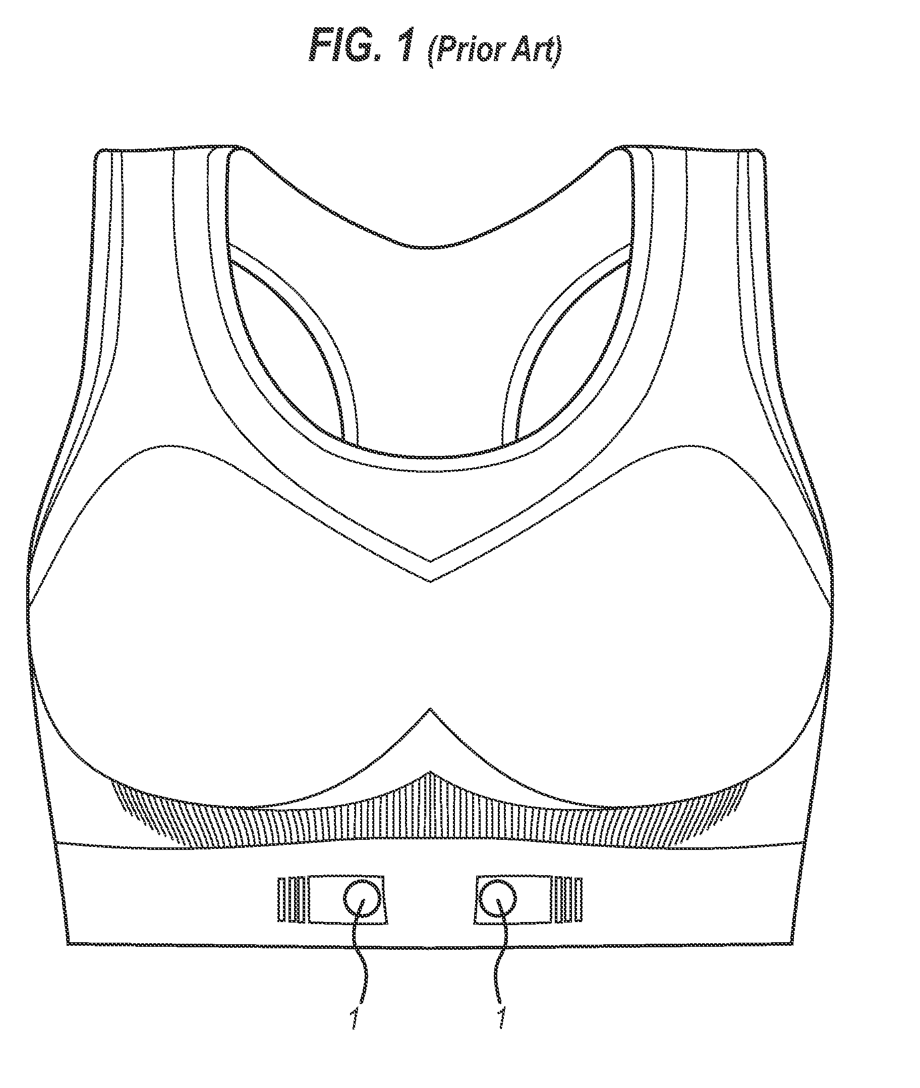
The position of the bra relative to the wearer's body may change with movement of the wearer as the bra is not always well fitted due to the fact that there are only four size options.
The movement of the bra increases the risk of losing the heart rate signal.

Method used


Image

  • Bra and bra components
  • Bra and bra components
  • Bra and bra components

Examples


first embodiment

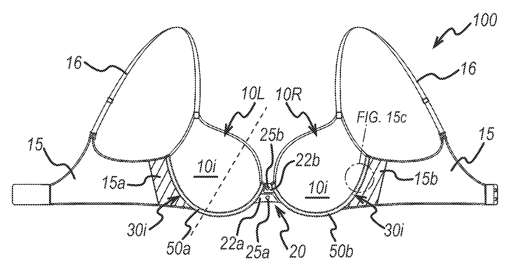
[0077]With reference to FIG. 2c, a bra 100 according to the present invention is an underwired bra 100 having underwire casings 50a, 50b attached to the inner surface 30i of the lower edge regions 30 of the breast cups. The underwire casings 50a, 50b house underwires (not shown in FIG. 2c).

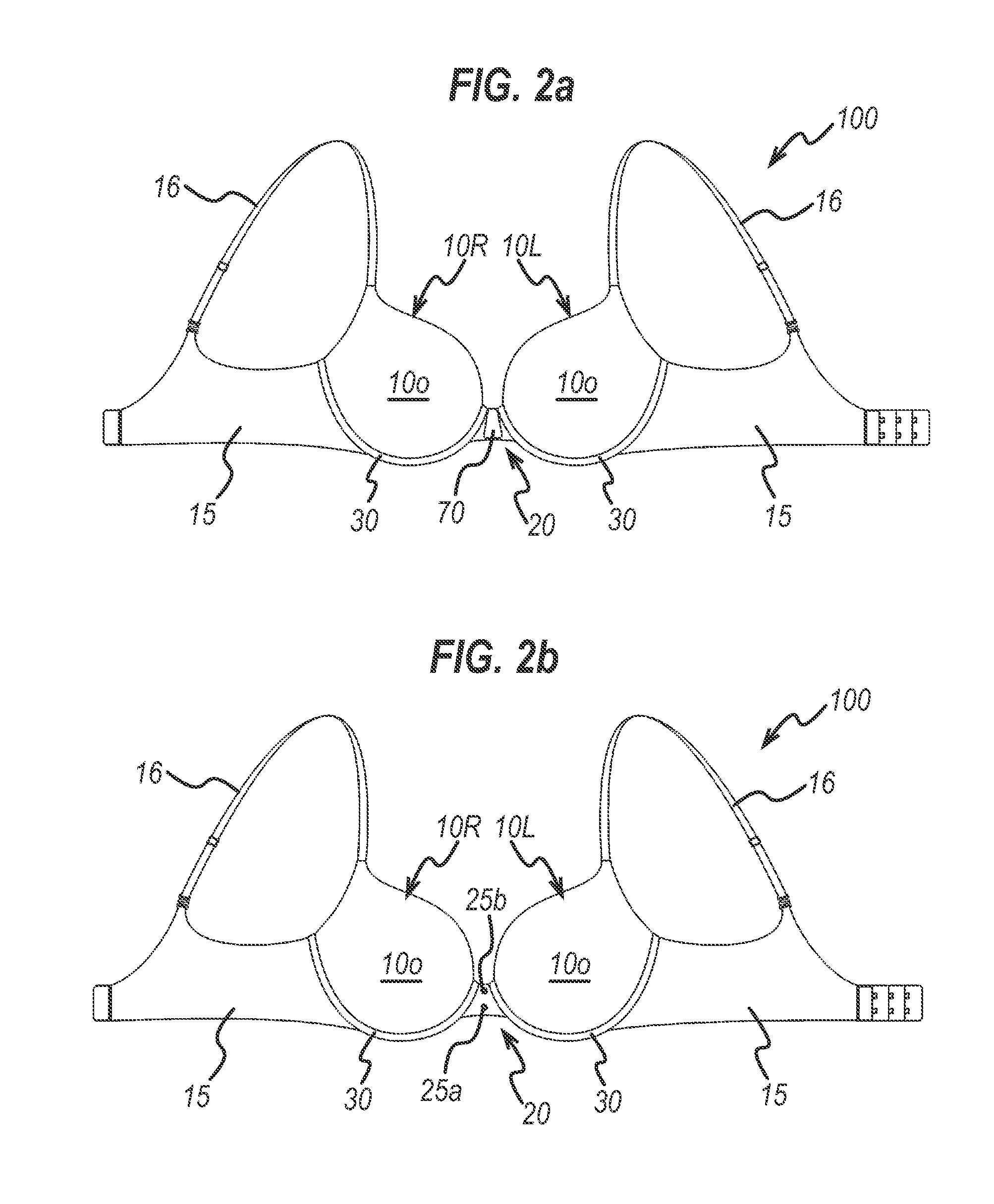
[0078]The underwire casings 50a, 50b comprise an electrically conductive fabric layer in contact with the wearer's skin to pick up electrical heart activity and transmit the electrical signals through the electrically-conductive fabric to the centre gore 20, attachment points 25a, 25b of the gore 20, and transmitter 70 (as shown in FIG. 2a).

[0079]As shown in the embodiment as illustrated in FIG. 2c, FIGS. 7a-7c and FIGS. 8a-8b, the centre gore 20 comprises two electrically conductive attachment points 25a, 25b (described in more detail later) for attachment of a transmitter, and two electrically conductive fabric portions 22a, 22b. The first electrically conductive fabric portion 22a is in contact...

second embodiment

[0086]FIGS. 4a and 4b illustrate an underwire casing 350 in accordance with the invention. FIG. 4a shows an end-on perspective view of the underwire casing 350 and FIG. 4b shows a cross-section of the underwire casing 350 shown in FIG. 4a. The underwire casing 350 is formed from an electrically conductive fabric layer 320 which surrounds an underwire 300. The underwire casing may be formed from a tube (as illustrated) of electrically conductive fabric 320 or may be formed from a U-shaped fabric layer 320 which is sewn along the open edge to provide a tube.

[0087]FIGS. 5a, 5b, 6a, 6b, 10a and 10b illustrate the attachment of the underwire casings of the first 250, 950 and second 350 embodiments to a breast cup of a bra, for example the breast cup 10L, 10R of the bra 100 illustrated in FIGS. 2a-c. FIGS. 5a, 5b, 6a, 6b, 10a and 10b are cross-sectional views of a breast cup 10L, 10R taken along the dotted line shown in FIG. 2c.

[0088]In particular, FIGS. 5a and 5b illustrate the attachme...


PUM


Abstract

A bra to enable monitoring of a wearer's heart rate. There is provided a bra comprising a left breast cup; a right breast cup; and a centre gore attached between the left and right breast cups. Each of the left and right breast cups comprises a lower edge region which is shaped to follow the shape of a wearer's breast and is shaped to be positioned below a wearer's breast to support the breast, and wherein the lower edge region comprises an electrically conductive fabric layer on the inner surface for contact with the user's skin. The centre gore comprises an attachment area for attachment of a transmitter and an electrically conductive pathway from the electrically conductive fabric of the lower regions of the breast cups to the attachment area. Bra components for providing electrical pathways are also provided.

Description

CROSS-REFERENCE TO RELATED APPLICATIONS[0001]This application claims priority to and the benefit of Chinese Patent Application No. 201510032889.6, filed on 22 Jan. 2015, and of PCT International Patent Application No. PCT / CN2014 / 000532, filed on 26 May 2014; the disclosures of these documents are incorporated herein by reference in their entirety.FIELD OF THE INVENTION[0002]The present invention relates in general to a bra which has a built-in mechanism to enable monitoring of, for example, the wearer's heart rate. The present invention also relates to the components of the bra which enable it to achieve its monitoring function.BACKGROUND[0003]There is a growing demand for equipment that enables an individual to monitor their own heart rate, for example when exercising to ensure they are exercising at the optimum heart rate.[0004]Chest heart rate monitors usually comprise two electrical sensors, a chest transmitter and a receiving device, e.g. a sports watch, a smart phone or cardio...

Claims


Application Information

Patent Timeline
IPC IPC(8): A41C3/00A61B5/00A61B5/0408
CPCA41C3/0064A41C3/0007A61B5/0006A61B5/6804A61B5/0408A41C3/122A41D13/1281A61B5/024A61B5/02438A61B5/02444A61B5/25
Inventor ZHANG, WENBO
Owner REGINA MIRACLE INTERNATIONAL (GROUP) LIMITED
Learn More