
Packaging Tray and Packaging Body

a packaging body and tray technology, applied in printing and other directions, to achieve the effect of convenient protection

Active Publication Date: 2015-11-12
SEIKO EPSON CORP
View PDF3 Cites 5 Cited by
  • Summary
  • Abstract
  • Description
  • Claims
  • Application Information

AI Technical Summary

Benefits of technology

The patent describes a packaging tray and a packaging body for a liquid container. The packaging tray has a restricting portion that prevents the handle portion from coming into contact with the packaging tray, thus preventing breakage of the liquid outlet portion of the liquid container from coming into contact with the packaging tray. This ensures that the liquid can be safely stored and transported without damage. The packaging body also protects the liquid container and the packaging tray, providing easy handling and safety.

Problems solved by technology

A liquid container provided with a handle portion has the problem in that some contrivance is necessary with respect to the distribution form from the standpoint of protecting the liquid container against breakage.

Method used


Image

  • Packaging Tray and Packaging Body
  • Packaging Tray and Packaging Body
  • Packaging Tray and Packaging Body

Examples


Embodiment Construction

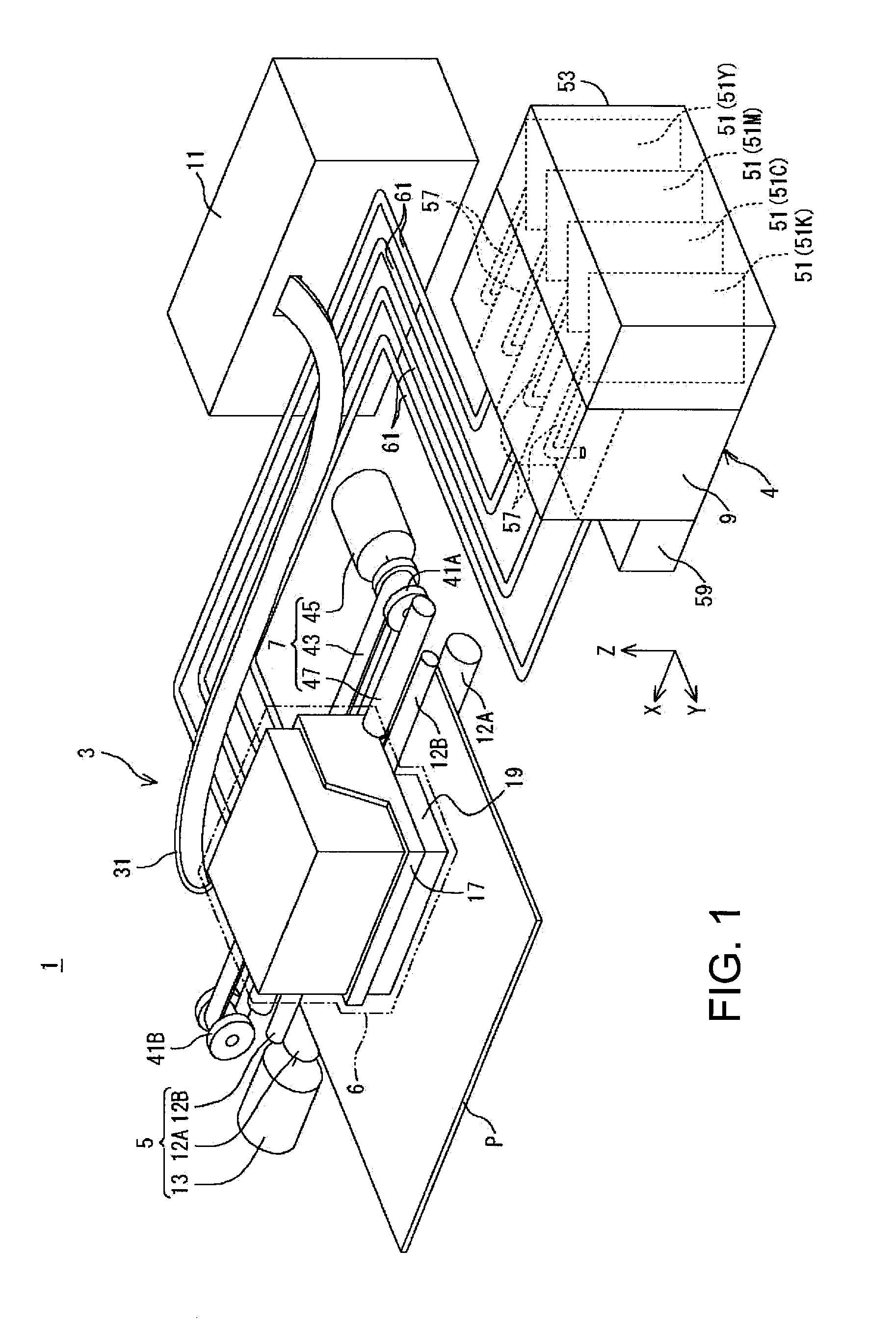
[0058]The following describes an embodiment of the invention with reference to the drawings, taking a liquid ejection system as an example. In the drawings, in order to show individual components in recognizable sizes, the components and members may be shown on different scales.

[0059]A liquid ejection system 1 according to the present embodiment has, as shown in FIG. 1, a printer 3, which is an example of a liquid ejection apparatus, and an ink supply apparatus 4, which is an example of a liquid supply apparatus. The printer 3 has a conveyance device 5, a recording unit 6, a moving device 7, a relay device 9, and a control unit 11. It should be noted that in FIG. 1, X-, Y-, and Z-axes, which are coordinate axes that are orthogonal to one another, are shown. The X-, Y-, and Z-axes may also be shown in the drawings described below as necessary. In the present embodiment, a state in which the liquid ejection system 1 is disposed in a horizontal plane (XY plane) defined by the X-axis an...


PUM


Abstract

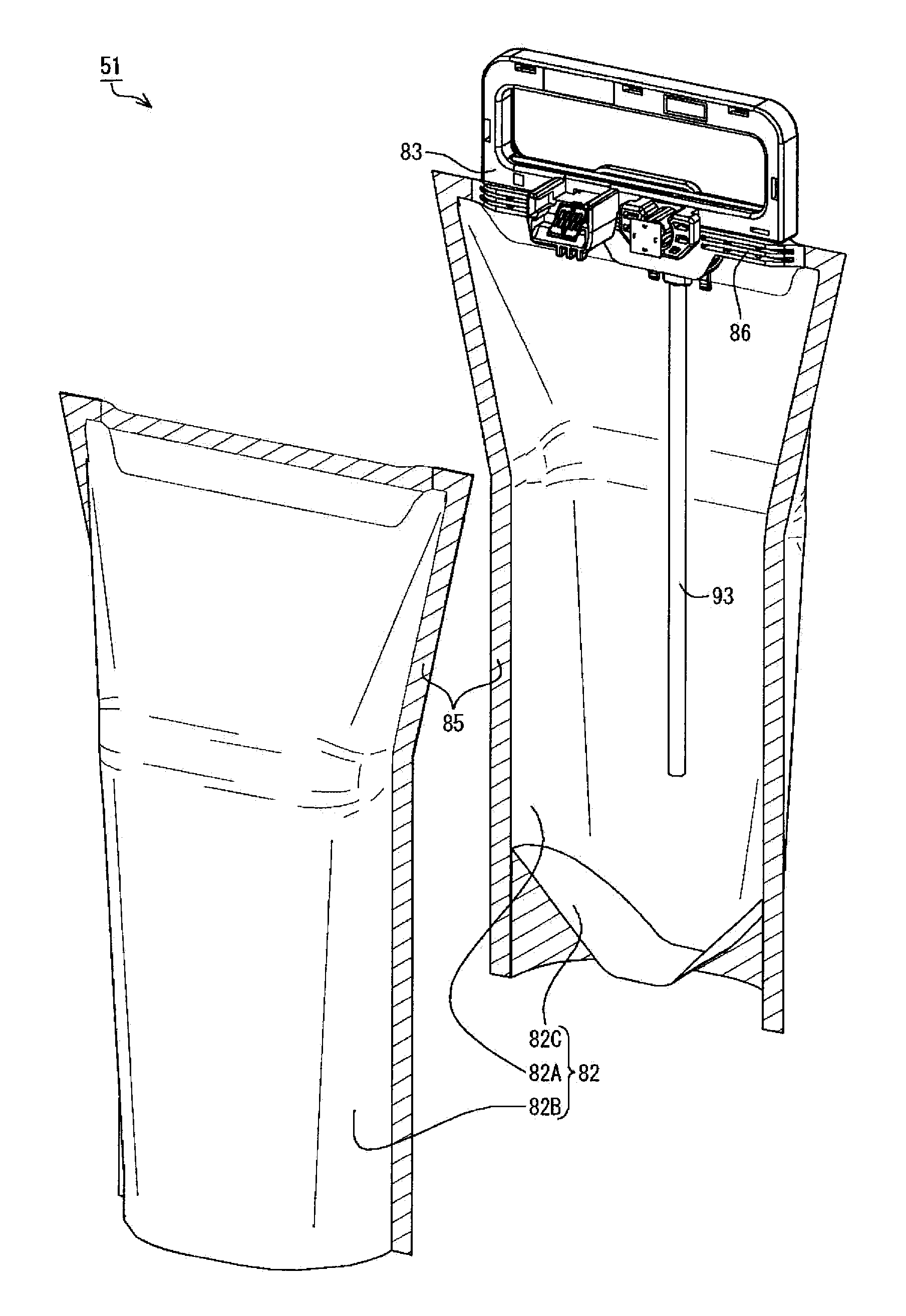
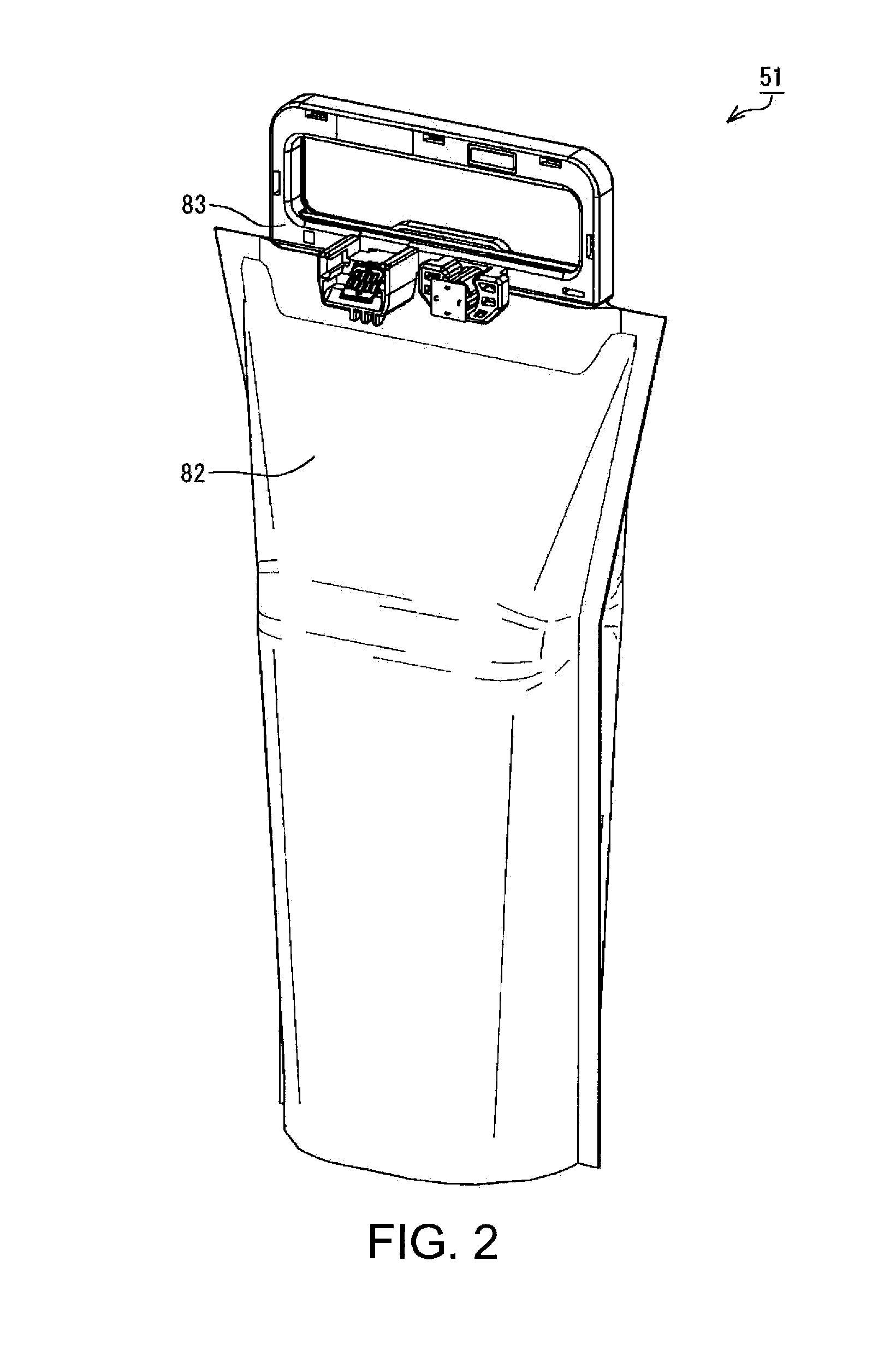
For a liquid container provided with a handle portion, some contrivance is necessary with respect to the distribution form from the standpoint of protecting the liquid container against breakage. In a packaging tray for an ink container, the ink container having a flexible ink bag, a supply portion provided in the ink bag, and a handle portion provided in the ink bag and protruding outward therefrom, the packaging tray includes a restricting portion that restricts the handle portion at such a position that a clearance is maintained between the supply portion of the ink container and the packaging tray.

Description

BACKGROUND[0001]1. Technical Field[0002]The present invention relates to a packaging tray, a packaging body, and the like.[0003]2. Related Art[0004]In recent years, inkjet printers are known as an example of liquid ejection apparatuses. Generally, inkjet printers can perform printing onto a print medium such as paper by directing jets of ink from a print head toward the print medium. With respect to such printers, in recent years, a configuration is known in which an external ink supply apparatus (liquid supply apparatus) is connected to the printer in order to stably supply ink to the print head (see JP-A-2009-202346, for example).[0005]In an external ink supply apparatus disclosed in JP-A-2009-202346, ink contained in an ink pack, which is an example of a liquid container, is supplied to a print head via an ink tube. This ink pack is flexible and is used in a state in which the ink pack is suspended from a support. If such an ink pack is provided with a handle portion (handle), th...

Claims


Application Information

Patent Timeline
Patent Type & Authority Applications(United States)
IPC IPC(8): B41J2/175
CPCB41J2/17533B41J2/17509B41J2/17513B41J2/17523B41J2/1753B41J2/17553B41J2002/17516
Inventor ISHIZAWA, TAKUKAWATE, HIROYUKI
Owner SEIKO EPSON CORP
Learn More