System and method for estimating collision damage to a car

a collision damage and estimation method technology, applied in the field of systems and methods for determining collision damage estimates, can solve the problems of vehicle inspection stations not configured to assess damage and/or provide an estimate for damage repair, damage to individual parts of the car, etc., to increase the accuracy of collision damage estimates, and reduce the effect of vehicle damag

Inactive Publication Date: 2015-10-15
AUDATEX
View PDF3 Cites 35 Cited by
  • Summary
  • Abstract
  • Description
  • Claims
  • Application Information

AI Technical Summary

Benefits of technology

The present invention provides a user interface for determining the estimate of the collision damage to a car by displaying a body part and allowing the user to define the outline of at least one damaged area through a user interface. The user interface includes options for different car models and the user can input the outline of the damaged area by defining its boundary on the body part. The estimate includes the cost and time for repairing the damage as defined by the user. The user interface also allows for the user to define the impact level of the damage and to determine if other parts of the car are impacted and need repair. The characteristics of the body part, such as its thickness, material, and repair accessibility, are also considered in generating the estimate to increase accuracy.

Problems solved by technology

However, the vehicle inspection station is not configured to assess the damage and / or provide an estimate for the repair of the damage.
The system is not configured, however, to determine in more detail the damage to individual parts of the car.
The system makes it possible to determine different levels of damage on body parts of a car, however, damage definition is limited to circular dents and a small number of given sizes.

Method used


Image

  • System and method for estimating collision damage to a car
  • System and method for estimating collision damage to a car
  • System and method for estimating collision damage to a car

Examples


Embodiment Construction

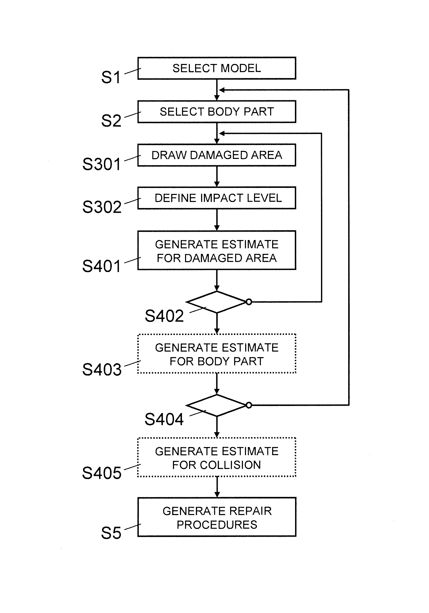
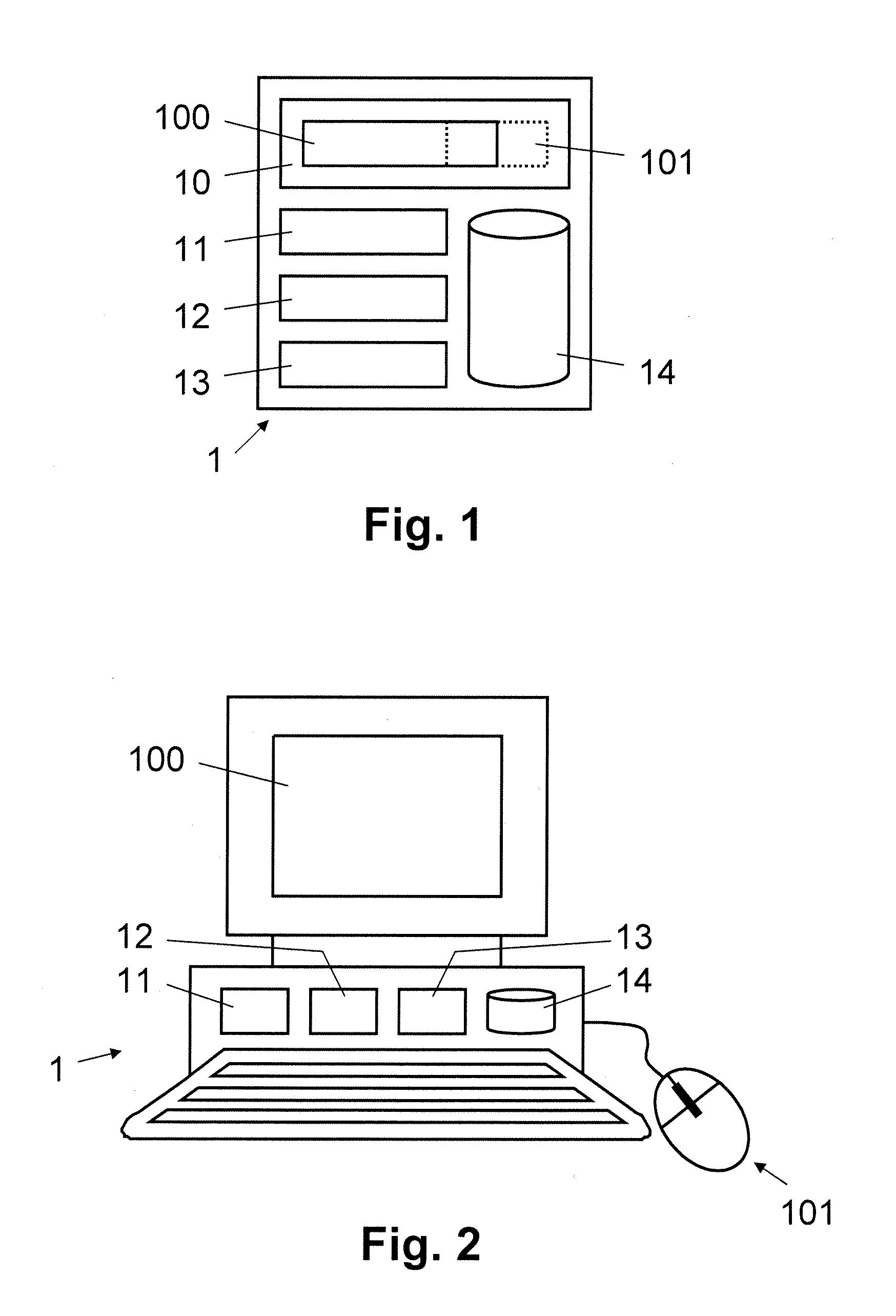
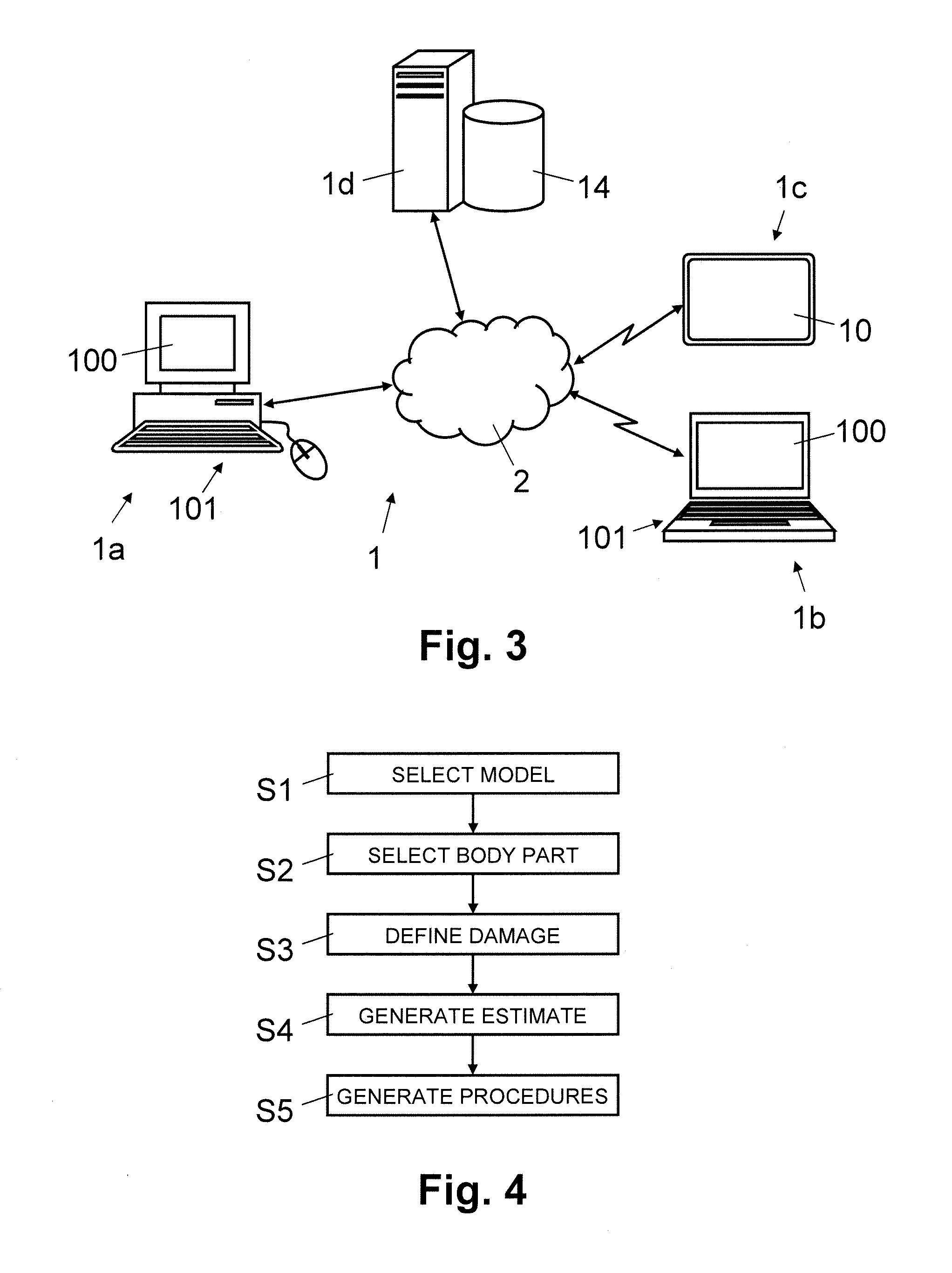
[0029]In FIGS. 1, 2, and 3, reference numeral 1 refers to a computer system for determining an estimate of collision damage to a car.

[0030]As illustrated in FIG. 1, the computer system 1 comprises a user interface 10. The user interface 10 comprises a display with a graphical user interface 100 displayed thereon and data entry elements 101. Depending on the embodiment, the data entry elements 101 comprise one or more keys, a keyboard, and / or a pointing device such as a touch pad, a track ball or a computer mouse enabling the user to enter instructions for controlling on the display or graphical user interface 100, respectively, the location of a position indicator such as an arrow 107′, a cursor, a pointer or another icon associated with a pointing tool 107 or a drawing tool 108, 108′, respectively. Alternatively, the display is a touch or multi-touch sensitive display having integrated the data entry elements 101 in the display or graphical user interface 100, respectively.

[0031]As...


PUM


Abstract

For determining an estimate of the collision damage to a car, a body part (3) of the car is displayed in a user interface (100). Through the user interface (100), input is received from the user for drawing on the body part (3) one or more damaged areas (4c, 5c). Specifically, the damaged areas (4c, 5c) are defined in each case by an outline of the damaged areas (4c, 5c), drawn on the body part (3) by way of a drawing tool (108, 108′), or as detected from an image. Subsequently, an estimate of the repair cost (C) and the repair time (T) is generated for the user, based on the damaged area (4c, 5c) drawn on the body part (3). Enabling the user to define the outlines of damaged areas (4c, 5c) makes it possible to define and estimate efficiently, flexibly, and accurately collision damage to a car.

Description

FIELD OF THE INVENTION[0001]The present invention relates to a system and a method for determining an estimate of collision damage to a car. Specifically, the present invention relates to a computer system and a computer-implemented method for determining an estimate of the collision damage to a car using a user interface to display a body part of the car.BACKGROUND OF THE INVENTION[0002]Typically, for car repair facilities, car insurance firms and damage appraisers, it is necessary to obtain an appraisal of the damage to a car (i.e. an automobile) resulting from a collision. It is particularly important to determine efficiently and accurately an estimate of the collision damage, including the time and / or cost for repairing the damage to the car.[0003]US2006 / 0114531 describes a vehicle inspection station that uses several cameras to capture images of a car. For detecting whether a car has damage, at least a portion of an image is compared with a previously stored image of the vehicl...

Claims


Application Information

Patent Timeline
Patent Type & Authority Applications(United States)
IPC IPC(8): G06Q40/08B62D65/00G06F3/0481G06F3/0484G06F3/0482
CPCG06Q40/08G06F3/04842B62D65/005G06F3/04847G06F3/04817G06F3/0482G06Q10/0631
Inventor GONZALEZ MIRANDA, JORGE FERNANDOALARCON ALCOLEA, JUAN JOSE
Owner AUDATEX
Why Eureka
Try Eureka