
Robot control device for controlling robot moved according to applied force

Active Publication Date: 2015-10-15
FANUC CORP
View PDF3 Cites 17 Cited by
  • Summary
  • Abstract
  • Description
  • Claims
  • Application Information

AI Technical Summary

Benefits of technology

The present invention is a robot control device that allows the robot to pass through near singular configurations, such as positions where it cannot be moved or controlled. It uses a near-singular configuration determination unit to determine whether to switch the control mode to control the position of each axis of the robot or the tip of the robot. The invention also allows the robot to pass through a position to which it cannot be moved by moving the position and / or posture of the tip of the robot arm on the orthogonal coordinate system. The invention also simplifies the movement operation for each axis by selecting at least one appropriate axis as an operation axis. It also allows the robot to pass through a position in another configuration, such as a different position in the workspace, by applying a force to the tip of the robot. The invention also allows for the unintentionally significant rotation of the rotation axis when moving the position on the orthogonal coordinate system.

Problems solved by technology

In the position and / or the posture of the tip thereof near such a singular configuration, it tends to be difficult to change the position and / or the posture thereof on the orthogonal coordinate system, there can be a axis that moves at an excessive velocity, or movement operation of the robot tends to be unstable in positional control.
Under such circumstances, an operator may be in danger during direct teaching.

Method used


Image

  • Robot control device for controlling robot moved according to applied force
  • Robot control device for controlling robot moved according to applied force
  • Robot control device for controlling robot moved according to applied force

Examples


first embodiment

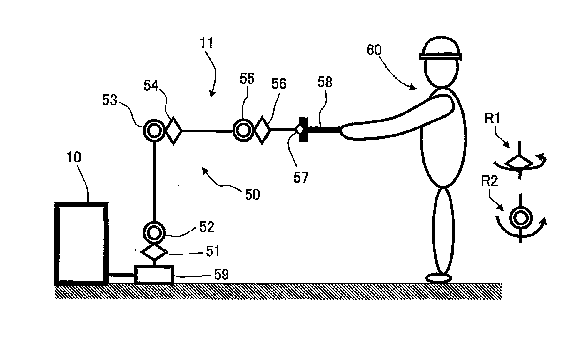
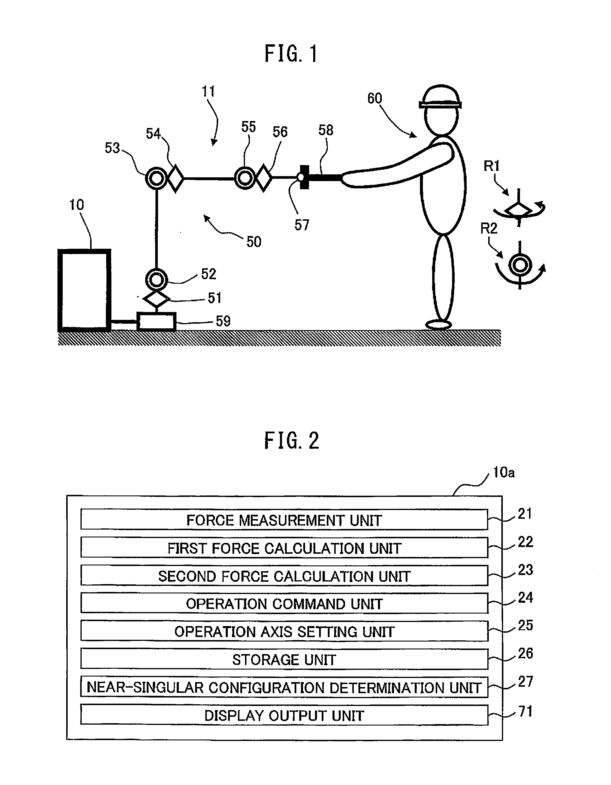
[0084]FIG. 2 is a diagram functionally depicting a structure of a robot control device 10a according to the present invention. As depicted in the drawing, the robot control device 10a includes the force measurement unit 21 described later, a first force calculation unit 22, a second force calculation unit 23, an operation command unit 24, an operation axis setting unit 25, a storage unit 26, a near-singular configuration determination unit 27, and a display output unit 71.

[0085]The force measurement unit 21 measures a net force applied to the tip 58 of the robot 50 by the operator 60. As described above, the force measurement unit 21 compensates, as needed, for the influence of the tool or the maneuvering device attached to the tip 58 of the robot 50 or a gripped object such as a workpiece caused due to gravity, inertia force (including Coriolis force and Gyroscopic precession), and the like.

[0086]The influence of the gravity and the inertia force caused by the object attached to th...

second embodiment

[0255]FIG. 18 is a diagram functionally depicting a structure of a robot control device 10b according to the present invention. As depicted in the drawing, the robot control device 10b includes a force measurement unit 21, a first force calculation unit 22, a second force calculation unit 23, an operation command unit 24, an operation axis setting unit 25, a storage unit 26, a axis position state determination unit 28, and a display output unit 71.

[0256]The robot control device 10b is adapted to use the axis position state determination unit 28, as an alternative to the near-singular configuration determination unit 27 of the robot control device 10a, so as to switch between the first control mode for controlling the position and / or the posture of the tip 58 of the robot 50 and the second control mode for controlling the position of each axis of the robot 50.

[0257]In addition, the operation axis setting unit 25 and the operation command unit 24 are adapted to use the axis position s...

third embodiment

[0292]In a robot control device 10 according to the present invention, the operation axis setting unit 25 further preferably sets a moving direction of one or more operation axes determined according to the direction of a force applied to the one or more operation axes on the basis of the direction of the force applied to the axes as the one or more operation axes and the moving direction of the axes as the one or more operation axes immediately before switching or when switched from the first control mode for moving the position and / or the posture on the orthogonal coordinate system to the second control mode for moving the position of each axis.

[0293]When a moving motion before going into the second control mode from the first control mode is not considered, there can be a feeling of discomfort, a feeling of oppression, and difficulty in operation. Moreover, depending on the movement operation of the tip 58 of the robot 50 on the orthogonal coordinate system, states associated wit...


PUM


Abstract

An operation command unit of a robot control device includes a first control mode that, when a near-singular configuration determination unit determines that a robot is not near a singular configuration, outputs an operation command for moving a position and / or a posture of the tip of the robot on the basis of an operation force calculated by a first force calculation unit and a second control mode that, when the near-singular configuration determination unit determines that the robot is near the singular configuration, outputs an operation command for moving the position of an operation axis set by an operation axis setting unit on the basis of an operation force calculated by a second force calculation unit and a moving direction set by the operation axis setting unit.

Description

BACKGROUND OF THE INVENTION[0001]1. Field of the Invention[0002]The present invention relates to a robot control device for controlling a robot moved according to a force applied to the robot. More specifically, the invention relates to a robot control device of a robot system that moves a robot on the basis of a force applied to the robot that includes a plurality of axes.[0003]2. Description of the Related Art[0004]Direct teaching is known as a robot operation method for moving a robot by applying a force to the robot or a method for teaching a position by moving the robot. In such a case, force is applied in a direction to which the robot is desired to be moved to directly guide the robot, whereby the robot can be moved to a desired position and / or a desired posture on an orthogonal coordinate system.[0005]Japanese Laid-open Patent Publication No. S56-85106 discloses a method for moving a position and a posture of a tip of a robot arm on the basis of a signal generated by a force...

Claims


Application Information

Patent Timeline
IPC IPC(8): B25J9/16B25J13/06G06F17/16
CPCB25J9/161G06F17/16G05B2219/35438B25J9/1694B25J13/065B25J9/0081B25J9/1615B25J9/1633B25J13/085
Inventor IWATAKE, TAKAHIRO
Owner FANUC CORP
Learn More