Navigation with 3D localization using 2d images

a technology of 3d localization and 2d images, applied in the field of navigation with 3d localization using 2d images, can solve the problems of difficult or impossible to perceive exactly, two-dimensional images may not properly convey the true position or orientation of objects, and the difficulty of navigating a catheter in a three-dimensional environment using only a two-dimensional fluoroscopy imaging projection

Inactive Publication Date: 2015-08-13
HANSEN MEDICAL INC
View PDF7 Cites 98 Cited by
  • Summary
  • Abstract
  • Description
  • Claims
  • Application Information

AI Technical Summary

Benefits of technology

[0004]In one aspect, a method for facilitating a medical or surgical procedure in an operating site in a body of a patient may involve: displaying a first point on a first two-dimensional image of the operating site into which an elongate, flexible catheter device is inserted in response to a first user input; mapping the first point on at least a second two-dimensional image of the operating site, the second two-dimensional image being oriented at a non-zero angle with respect to the first two-dimensional image; displaying a first line on the second image that projects from the first point; displaying a second point on the second image in response to a second user input; and determining a three-dimensional location within the operating site, based on the first line and the second point on the second image.

Problems solved by technology

Navigating a catheter in a three-dimensional environment using only a two-dimensional fluoroscopy imaging projection is a challenging task, primarily because two-dimensional images, by definition, cannot show depth associated with the image shown.
Accordingly, two-dimensional images may not properly convey a true position or orientation of objects.
In the context of catheter systems, this can lead to errors, for example, where it is difficult or impossible to perceive exactly how a catheter or component thereof is bent or oriented within an operating site of a patient.
While some catheter systems include three-dimensional localization, a number of catheter systems do not support three-dimensional localization.
Additionally, three-dimensional localization may not be practical for all applications.

Method used


Image

  • Navigation with 3D localization using 2d images
  • Navigation with 3D localization using 2d images
  • Navigation with 3D localization using 2d images

Examples


Embodiment Construction

[0025]Illustrative examples are shown in detail in the drawings below. Although the drawings represent the specific exemplary illustrations disclosed herein, the drawings are not necessarily to scale, and certain features may be exaggerated to better illustrate and explain an innovative aspect of an example. Further, the examples described herein are not intended to be exhaustive or otherwise limiting or restricting to the precise form and configuration shown in the drawings and disclosed in the following detailed description.

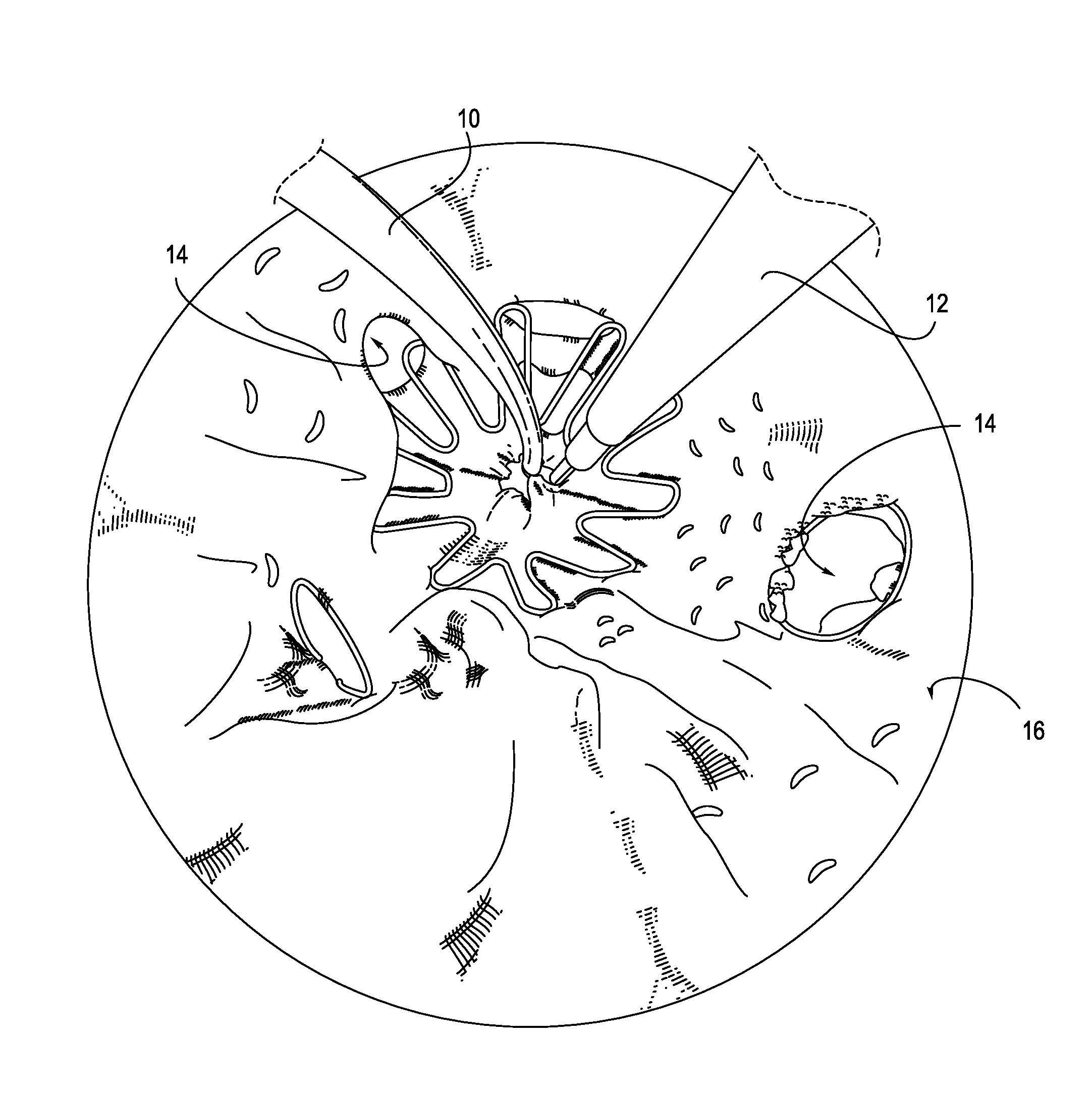
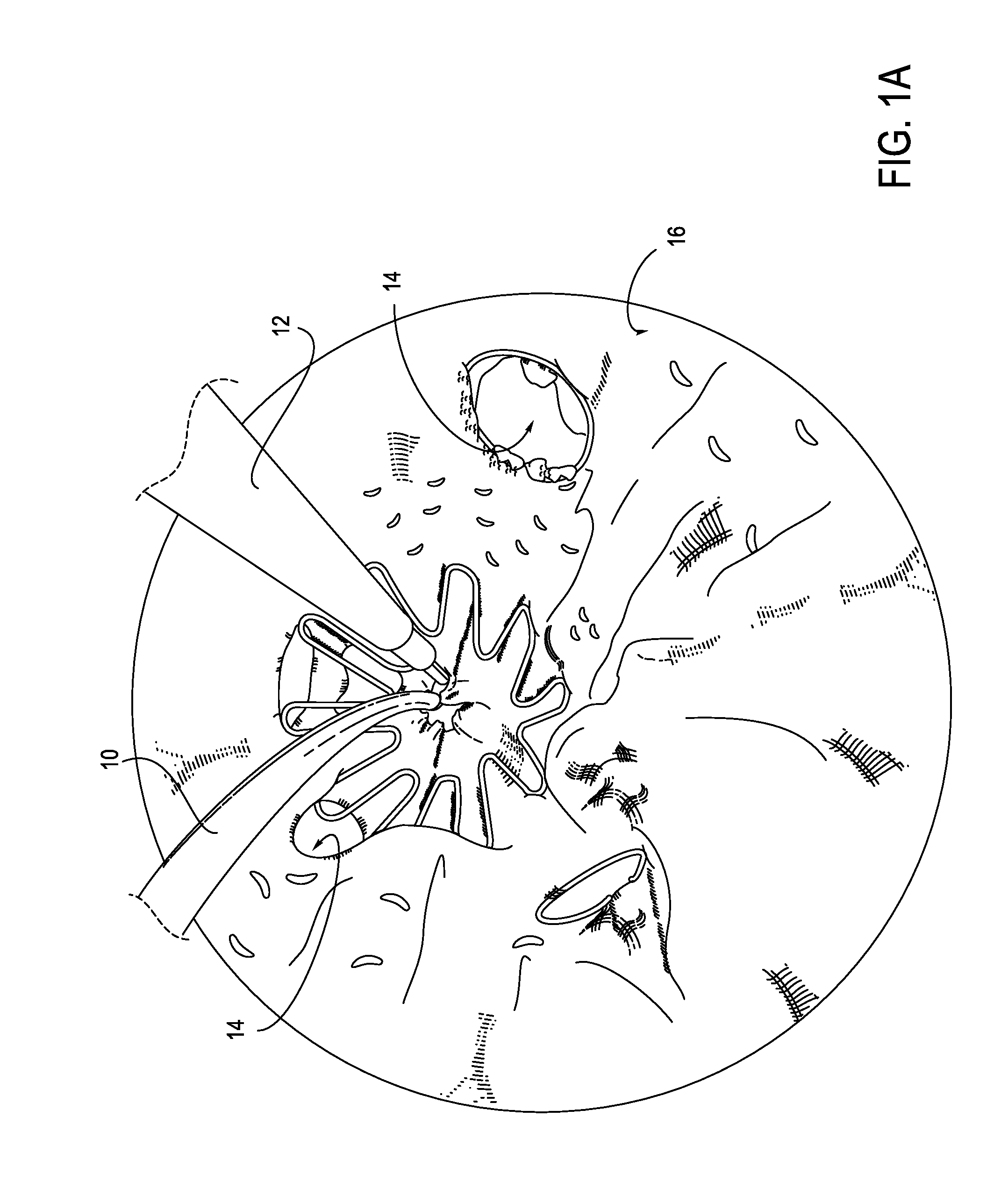
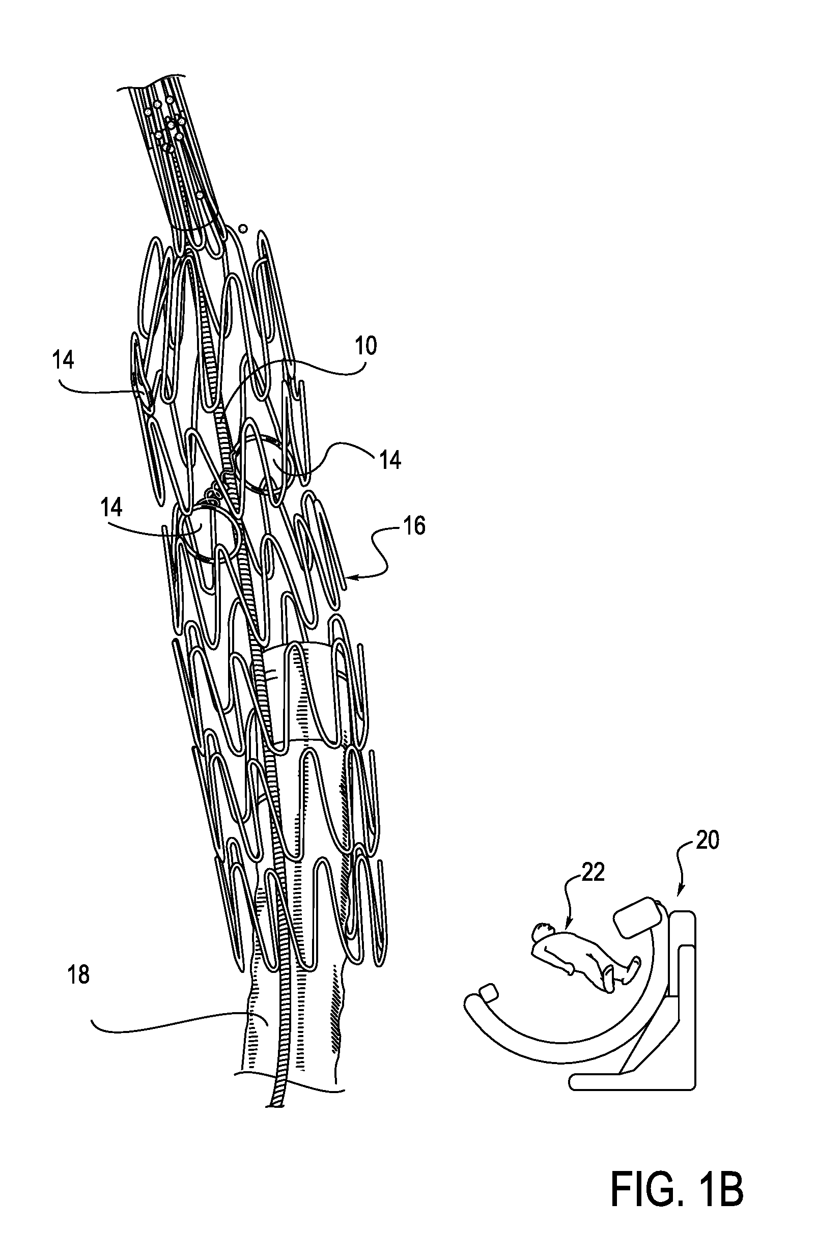
[0026]The description below and associated drawings generally describe ways of marking points or features in three-dimensional space to aid navigation of an elongated member, e.g., a catheter, without requiring a three-dimensional model.

[0027]In one exemplary illustration, a user interface and mathematical calculations are described that allow the physician to specify target anatomy in more than one two-dimensional view, e.g., using fluoroscopy. For example, th...


PUM


Abstract

A method for facilitating a medical or surgical procedure in an operating site in a body of a patient may involve: displaying a first point on a first two-dimensional image of the operating site into which an elongate, flexible catheter device is inserted in response to a first user input; mapping the first point on at least a second two-dimensional image of the operating site, the second two-dimensional image being oriented at a non-zero angle with respect to the first two-dimensional image; displaying a first line on the second image that projects from the first point; displaying a second point on the second image in response to a second user input; and determining a three-dimensional location within the operating site, based on the first line and the second point on the second image.

Description

CROSS-REFERENCES TO RELATED APPLICATIONS[0001]This application claims priority to U.S. Provisional Application No. 61 / 937,203, filed on Feb. 7, 2014 and entitled “NAVIGATION WITH 3D LOCALIZATION USING 2D IMAGES,” the content of which is incorporated by reference herein in its entirety.BACKGROUND[0002]Navigating a catheter in a three-dimensional environment using only a two-dimensional fluoroscopy imaging projection is a challenging task, primarily because two-dimensional images, by definition, cannot show depth associated with the image shown. Accordingly, two-dimensional images may not properly convey a true position or orientation of objects. In the context of catheter systems, this can lead to errors, for example, where it is difficult or impossible to perceive exactly how a catheter or component thereof is bent or oriented within an operating site of a patient.[0003]While some catheter systems include three-dimensional localization, a number of catheter systems do not support th...

Claims


Application Information

Patent Timeline
Patent Type & Authority Applications(United States)
IPC IPC(8): A61B19/00A61F2/95A61F2/88A61B5/05A61B5/00A61B17/12A61M25/09
CPCA61B19/5244A61B2019/5229A61F2/95A61M25/09A61B5/05A61B5/6852A61B17/12118A61B19/56A61F2/88A61B2019/5238A61B2019/5265A61B2019/5291A61B2017/00292A61B2019/5287A61B17/12013A61B5/061A61B2505/05A61B2090/364A61B90/361A61B2090/3762A61B2090/367
Inventor WALKER, SEAN P.PARK, JUNE
Owner HANSEN MEDICAL INC
Why Eureka
Try Eureka