
Electric sweeping washing device

a washing device and electric technology, applied in the field of electric sweeping washing devices, can solve the problems of inability to wash and clean the floor thoroughly, and inability to remove tiny dust and smears from the floor or rug, etc., to achieve the effect of easy and fast cleaning of the floor and the rug, cost saving, labor saving and space saving

Inactive Publication Date: 2015-03-26
LIN CHING CHI
View PDF0 Cites 57 Cited by
  • Summary
  • Abstract
  • Description
  • Claims
  • Application Information

AI Technical Summary

Benefits of technology

The Electronics Sweep Washing device has multiple functions. It allows users to easily and quickly sweep and wash floors and rugs in a cost-saving, labor-saving, and space-saving way. The device removes smears and tiny dust from the floor while sweeping and can also function as an electric window washer. It prevents dirty water from landing on the floor.

Problems solved by technology

The floor sweeping machines remove dust from the floor by sweeping and vacuum cleaning the floor, but fail to remove tiny dust and smear from the floor or rug.
However, during the aforesaid cleaning process, as long as dirty water which results from scrubbing the floor remains on the floor, the floor will still look dirty after the dirty water has dried up, whereas a portion of the floor is likely to absorb water or has a crack, and in consequence dirty water will be kept inside the crack.
Hence, it is impossible to wash and clean the floor thoroughly.
Since the rug absorbs water, water must not be sprayed onto the rug; hence, it is impossible for the robotic floor washing machine to remove a smear from the rug.
From a user's perspective, conventional tools for use in washing windows, floors, and rugs are difficult to operate, time-consuming, and laborious, not to mention that they have to work in conjunction with various single-function machines.

Method used


Image

  • Electric sweeping washing device
  • Electric sweeping washing device
  • Electric sweeping washing device

Examples


first embodiment

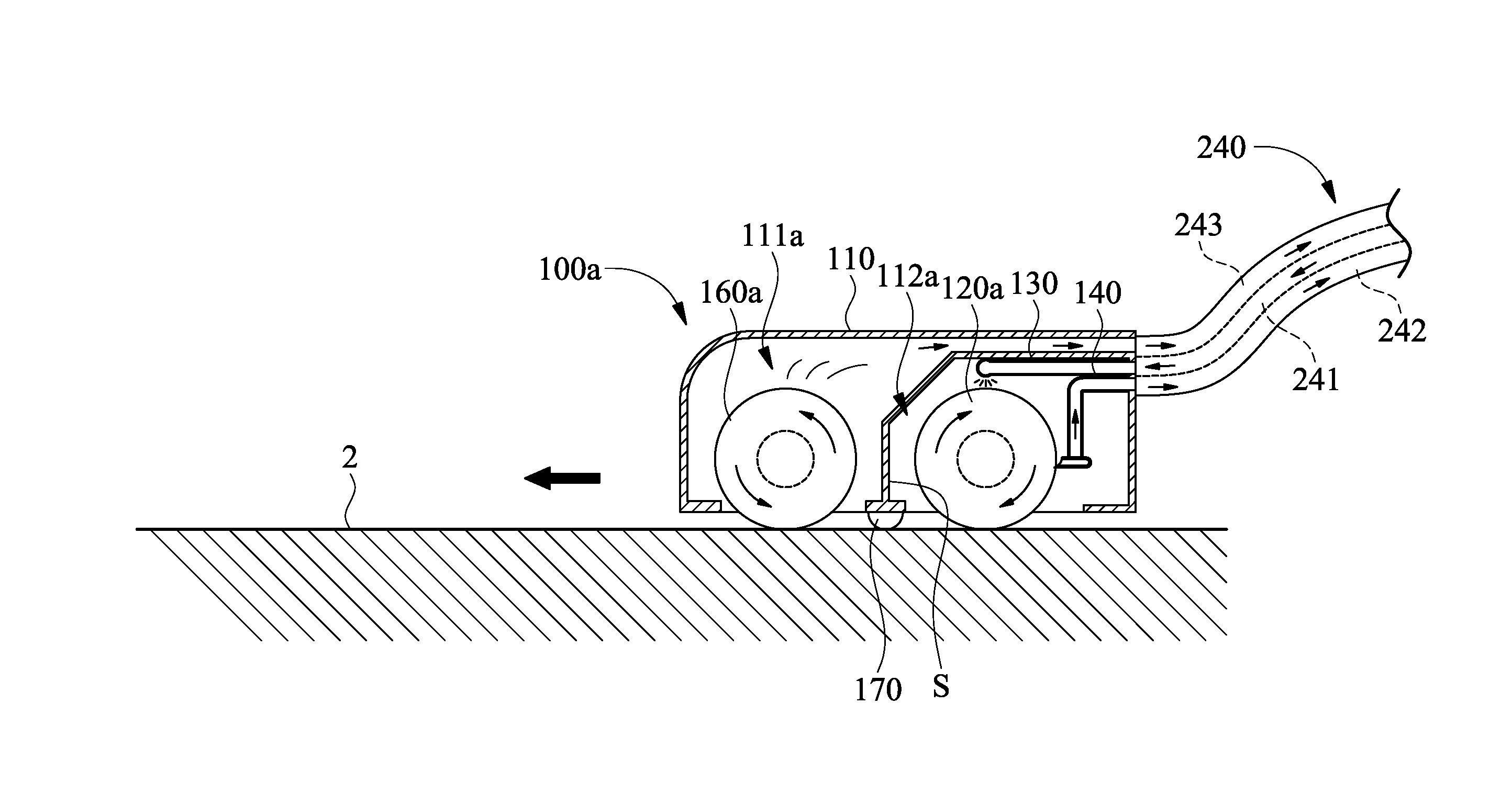
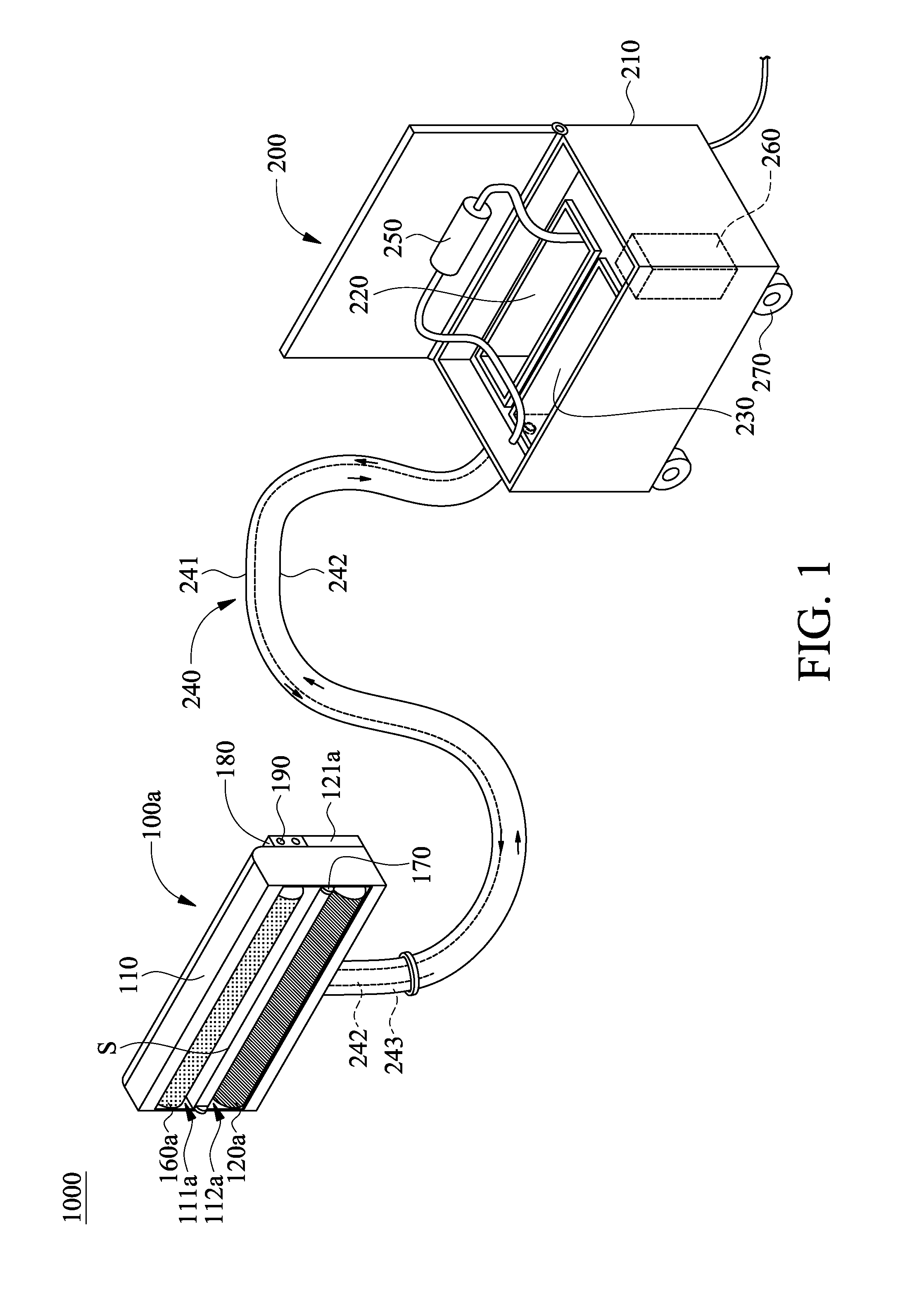
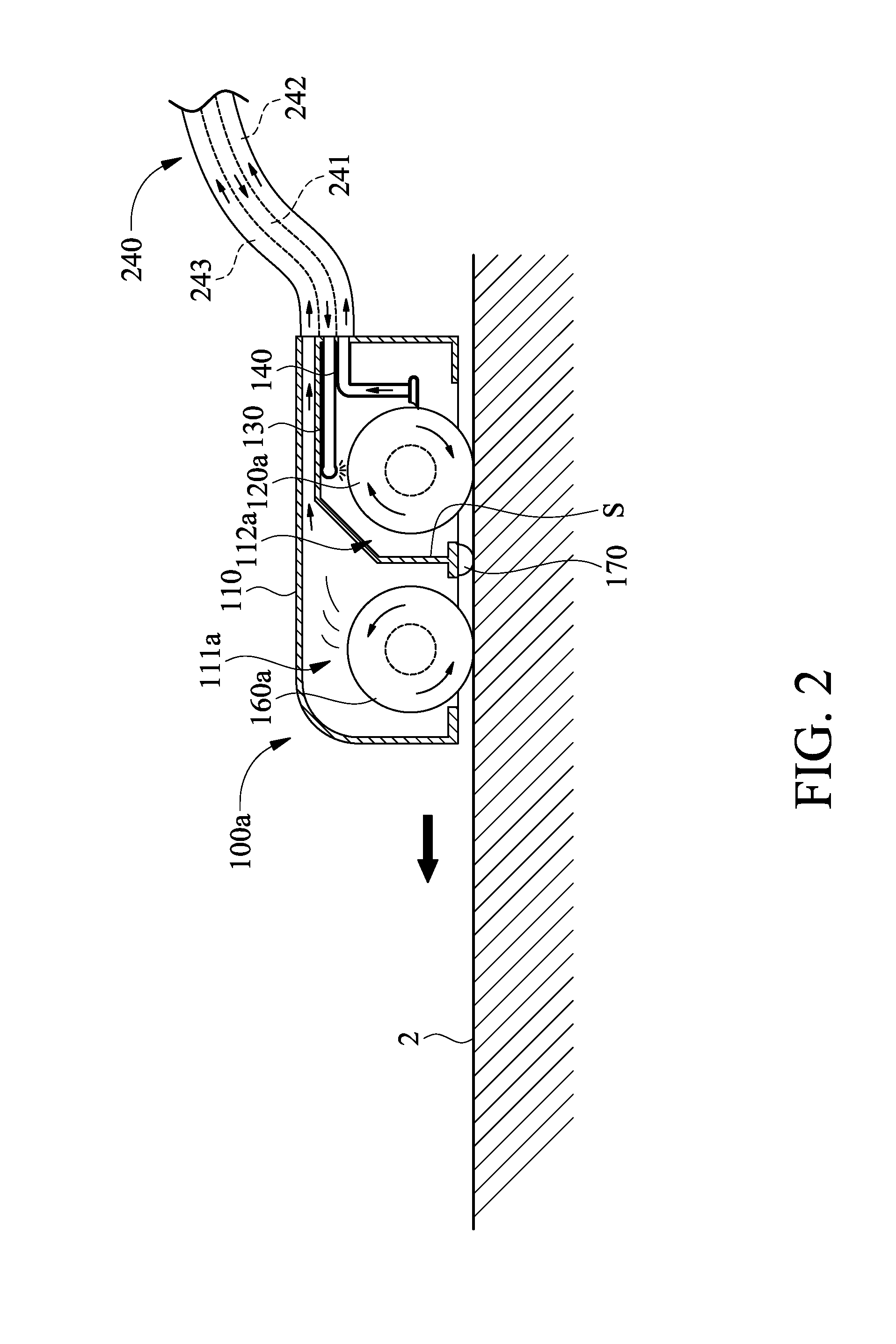
[0031]Referring to FIG. 1 through FIG. 4, there are shown schematic views of an electric sweeping washing device 1000 according to the present invention. The electric sweeping washing device 1000 is for use in sweeping and washing a floor 2 (such as a floor and a rug.) The electric sweeping washing device 1000 comprises a sweeping washing brush 100a and a water collection system design 200.

[0032]The sweeping washing brush 100a comprises a body 110, a sweeping roller brush 160a, an auxiliary wheel 170, a water absorbing scrubbing roller brush 120a, a sprinkler head 130, and an water absorbing scraper 140.

[0033]The body 110 has a separating board S for demarcating and separating a sweeping washing brush front 111a from a sweeping washing brush rear 112a. Both the opening of the sweeping washing brush front 111a and the opening of the sweeping washing brush rear 112a face the floor 2.

[0034]The sweeping roller brush 160a is disposed inside the sweeping washing brush front 111a and drive...

second embodiment

[0061]Referring to FIG. 9 through FIG. 13, there are shown schematic views of an electric sweeping washing device 3000 according to the present invention. The electric sweeping washing device 3000 is for use in washing a window 1. The electric sweeping washing device 3000 comprises a washing brush 100 and a water collection system design 200.

[0062]The washing brush 100 comprises a body 110, a water absorbing scrubbing roller brush 120, and a sprinkler head 130.

[0063]The body 110 has a washing brush casing 111. The opening of the washing brush casing 111 faces the window 1, as shown in FIG. 13.

[0064]The water absorbing scrubbing roller brush 120 is disposed inside the washing brush casing 111 and driven by a washing brushed motor 121 to rotate.

[0065]The sprinkler head 130 is disposed inside the washing brush casing 111. The sprinkler head 130 faces the water absorbing scrubbing roller brush 120 and washes off tiny dust and dirty water otherwise adhered to the water absorbing scrubbin...

third embodiment

[0077]Referring to FIG. 9 through FIG. 13, there are shown schematic views of operation of the electric sweeping washing device according to the present invention, wherein the washing brush 100 and the window 1 are shown.

[0078]During the process of cleaning the window 1 with the water absorbing scrubbing roller brush 120, the clean water stored in the clean water chamber 220 is taken in by the spray motor 250, delivered by the spray tube 241, and sprinkled by the sprinkler head 130 onto the water absorbing scrubbing roller brush 120 to thereby remove dust or dirt from the water absorbing scrubbing roller brush 120.

[0079]The air intake motor 260 reduces the internal pressure of the dirty water chamber 230 to vacuum pressure, such that the water absorbing scraper 140 rakes dust-containing or dirt-containing dirty water on the water absorbing scrubbing roller brush 120 and delivers the dirty water to the water absorbing tube 242, and in consequence the dirty water is collected in the d...


PUM


Abstract

An electric sweeping washing device includes a sweeping washing brush and a water collection system design. The sweeping washing brush includes a body; a sweeping roller brush disposed anteriorly at the body; and a dust collecting box for raking dust; a water absorbing scrubbing roller brush disposed posteriorly at the body; a sprinkler head; and a water absorbing scraper for absorbing water from the water absorbing scrubbing roller brush and raking dirty water. The water collection system design includes a tank divided into a clean water chamber and the dirty water chamber, wherein the sprinkler head, the clean and dirty water chambers, a water absorbing scraper, and the dust collecting box are connected via tubes; a spray motor for withdrawing clean water from the clean water chamber and delivering it to the sprinkler head; and an air intake motor for providing vacuum pressure to the dirty water chamber.

Description

FIELD OF TECHNOLOGY[0001]The present invention relates to washing devices for sweeping and washing a floor concurrently or for washing window glass in an electrically driven manner, and more particularly, to an electric sweeping washing device for sweeping and scrubbing the floor and / or rug concurrently and washing windows.BACKGROUND[0002]Due to technological advancement, there is wide use of the existing art pertaining to cleaning, an indoor environment, such as the floor, with an automated cleaning machine, wherein control logic of a mobile robot enables the cleaning machine capable of vacuum cleaning or floor washing to roam within a space to be swept and cleaned the floor in an automated manner.[0003]The aforesaid conventional automated cleaning machines fall into two categories, namely floor sweeping machines and floor washing machines. The floor sweeping machines remove dust from the floor by sweeping and vacuum cleaning the floor, but fail to remove tiny dust and smear from t...

Claims


Application Information

Patent Timeline
IPC IPC(8): A47L11/40
CPCA47L11/4044A47L11/4013A47L11/4088A47L11/4041A47L1/02A47L11/26
Inventor LIN, CHING-CHI
Owner LIN CHING CHI
Learn More