
Real Time Approximation for Robotic Space Exploration

a robotic space and real-time approximation technology, applied in the field of robotics, can solve the problems of dizziness, nausea and disorientation in the human handler, and agonizingly slow progress of the robotic vehicle mission, and achieve the effect of not affecting the progress of the robotic vehicle, nausea or disorientation, and avoiding dizziness

Active Publication Date: 2015-02-26
STEPHENS JR KENNETH DEAN
View PDF10 Cites 22 Cited by
  • Summary
  • Abstract
  • Description
  • Claims
  • Application Information

AI Technical Summary

Benefits of technology

The invention describes a way to send humans to the moon using slave robots that can be controlled by those on the ground. The system uses a video display that allows the controllers to see what the proxy robot is doing in real-time, without getting sick or losing their perspective. This helps to make the exploration of the moon safer and more efficient, and can also improve the overall capabilities of the robot control system.

Problems solved by technology

By its very nature, space exploration involves delays in communication between bases on Earth and missions in remote locations such as the Moon and planets.
In the case of proxy robotics (above), wherein a human handler guides a proxy robot by “seeing” through that robot's “eyes,” the 2.6 second round trip delay between a “follow me” movement and its visual confirmation can result in dizziness, nausea and disorientation in the human handler.
Planetary exploration generates a far longer delay: between 3 and 22 minutes each way between Earth and Mars, for example, generally resulting in agonizingly slow progress for robotic vehicle missions as Mission Control issues a command and then waits 10 or 20 minutes for video confirmation that it has been successfully carried out.
With a communication delay measured in minutes rather than seconds, a robotic mission to Mars presents a bigger challenge when it comes to approximating times like 5, 10 or 15 minutes in the robot's future.

Method used


Image

  • Real Time Approximation for Robotic Space Exploration
  • Real Time Approximation for Robotic Space Exploration
  • Real Time Approximation for Robotic Space Exploration

Examples


Embodiment Construction

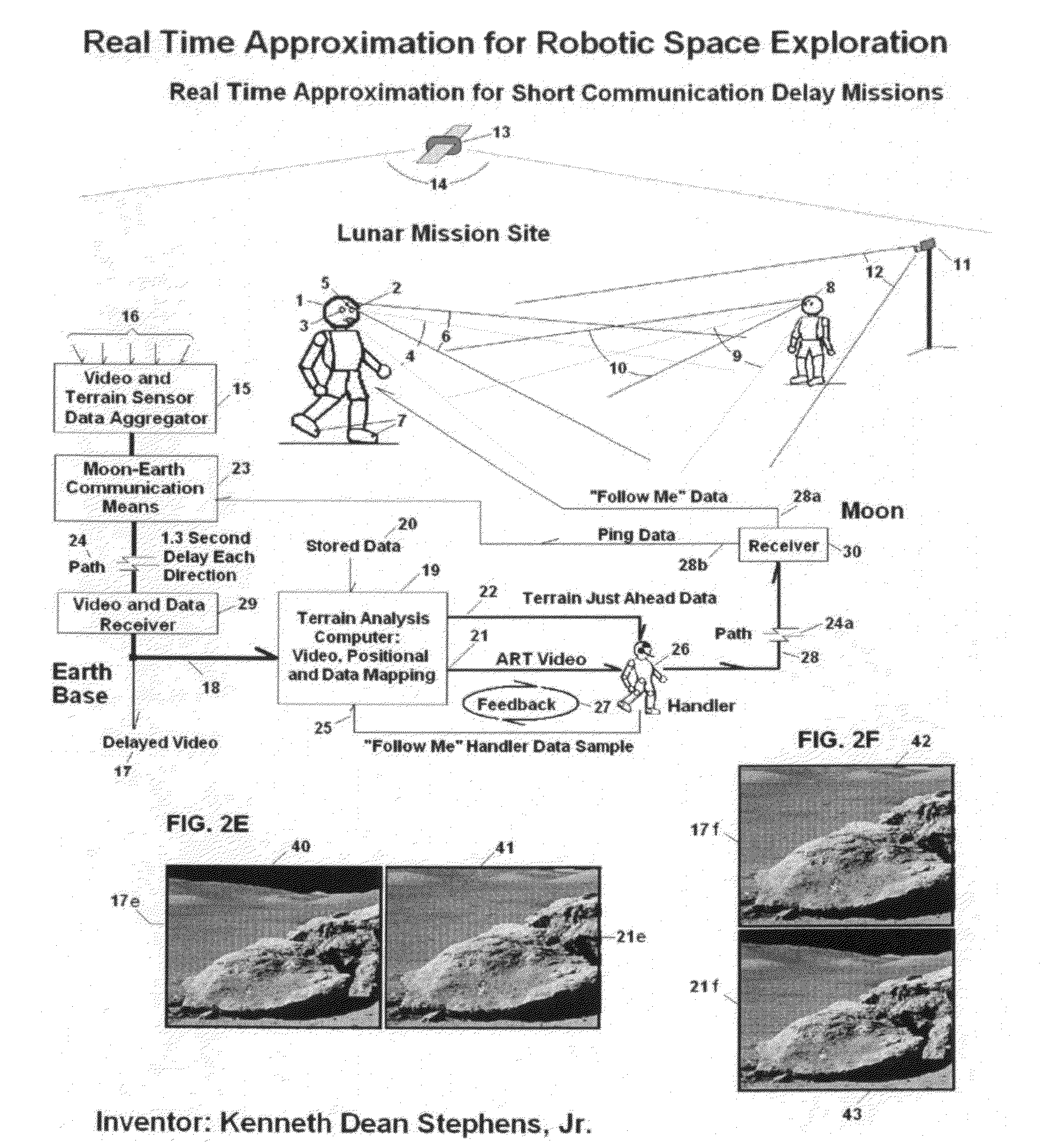
[0043]FIG. 1 depicts an exemplary proxy robot 1 in accordance with embodiments of the present invention on the surface of the Moon under the control of a human handler 26 on Earth. The proxy robot has two camera “eyes”2 and 3, that focus on an area 4 that the robot is directed to face, streaming live video to a video and terrain sensor data aggregator 15 and Earth-Moon communication means 23. The proxy robot may also contain other terrain sensors such as sensor 5 located in the center of the robot's head above the camera eyes. Sensor 5 scans a region 6 and may contain laser, radar or other ranging or mapping means. Terrain-just-ahead sensors 7 may also be located in the front of each of the robot's boots to map and warn of uneven terrain, rocks, pits and so forth that might hinder forward movement.

[0044]The general mission area may contain other proxy robots 8 which may also be directed to scan the terrain ahead of proxy robot 1, via video 9 and ranging / mapping means 10. In the draw...


PUM


Abstract

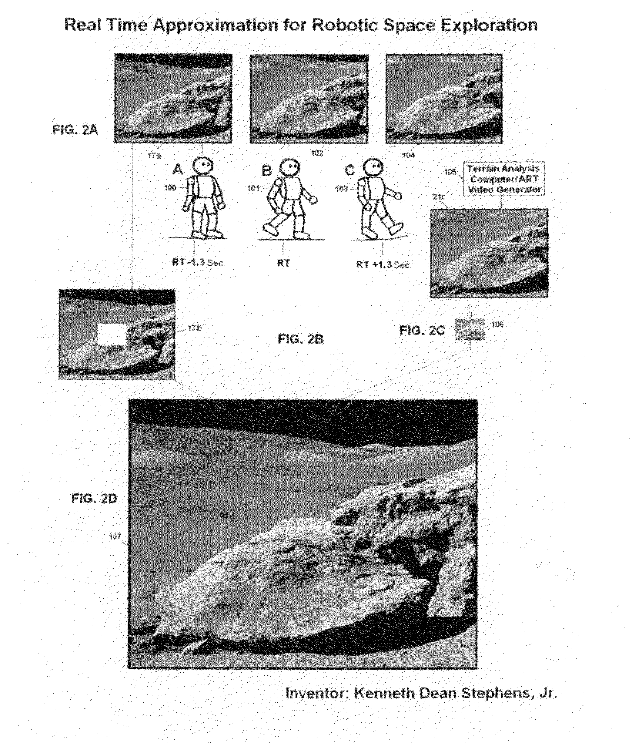
A system and method for guidance of a moving robotic device through an approximated real time (ART) virtual video stream is presented. The system and method includes at least one camera for collecting images of a terrain in a remote location, at least one terrain data collecting device for collecting data from a remote location, a memory for storing images from the plurality of cameras, a communication device for transmitting the images and data over a path and a computer configured to calculate a delay between the cameras and the receiver. The calculated delay causes the computer to retrieve images and data from the receiver and memory and consequently generate an approximate real-time video and data stream for displaying the terrain-just-ahead of a moving robotic device at a distance proportional to the calculated delay and the ART video and data stream is used to guide the moving robotic device.

Description

CLAIM OF PRIORITY[0001]The present invention claims priority to Provisional U.S. Application No. 61,711,750 filed on Oct. 10, 2012; entitled “Real Time Approximation for Robotic Space Exploration.”FIELD OF THE INVENTION[0002]The present claimed invention combines the fields of robotics with video and data mapping to create video approximation, as related to human proxy robot systems specifically and more generally to robotic communication and control.BACKGROUND OF THE INVENTION[0003]By its very nature, space exploration involves delays in communication between bases on Earth and missions in remote locations such as the Moon and planets. In the case of the Moon, there is a 1.3 second communication delay in each direction from and to the Earth, or 2.6 seconds round trip. In the case of proxy robotics (above), wherein a human handler guides a proxy robot by “seeing” through that robot's “eyes,” the 2.6 second round trip delay between a “follow me” movement and its visual confirmation c...

Claims


Application Information

Patent Timeline
IPC IPC(8): B25J9/16
CPCB25J9/1689B25J9/1697G05B2219/40116Y10S901/47G05B2219/40191Y10S901/01
Inventor STEPHENS, JR., KENNETH DEAN
Owner STEPHENS JR KENNETH DEAN
Learn More