Brake controller, elevator system and a method for performing an emergency stop with an elevator hoisting machine driven with a frequency converter

a technology of a brake controller and an elevator, which is applied in the direction of elevators, building lifts, transportation and packaging, etc., can solve the problems of inconvenience in placement, large size of relays, and disturbance of residents of buildings, so as to reduce also the frequency converter, and simplify the safety arrangement of the elevator. , the effect of reducing the size of the brake controller

Active Publication Date: 2015-02-26
KONE CORP
View PDF13 Cites 35 Cited by
  • Summary
  • Abstract
  • Description
  • Claims
  • Application Information

AI Technical Summary

Benefits of technology

[0010]The invention enables the integration of the brake controller into the DC intermediate circuit of the frequency converter of the hoisting machine of the elevator. This is advantageous because the combination of the frequency converter and the brake controller is necessary from the viewpoint of the safe operation of the hoisting machine of the elevator and, consequently, from the viewpoint of the safe operation of the whole elevator. In addition, the size of the brake controller and also of the frequency converter decreases, which enables space saving e.g. in an elevator system having no machine room. The brake controller according to the invention can also be connected as a part of the safety arrangement of an elevator via a safety signal, in which case the safety arrangement of the elevator is simplified and it can be implemented easily in many different ways. Additionally, the combination of the safety signal and the brake switching logic according to the invention enables the brake controller to be implemented completely without mechanical contactors, using only solid-state components. When eliminating contactors, also the disturbing noise produced by the operation of the contactors is removed. Most preferably the input circuit of the safety signal and the brake switching logic are implemented only with discrete solid-state components, i.e. without integrated circuits. In this case analysis of the effect of different fault situations as well as of e.g. EMC interference connecting to the input circuit of the safety signal from outside is facilitated, which also facilitates connecting the brake controller to different elevator safety arrangements.
[0011]Since the brake controller can be connected to the DC intermediate circuit of the frequency converter, the energy returning to the DC intermediate circuit in connection with motor braking of the elevator motor can be utilized in the brake control, which improves the efficiency ratio of the elevator. In addition, the main circuit of the brake controller becomes simpler. In addition to this, connecting the brakes in connection with an emergency stop caused by an electricity outage can be stepped by first disconnecting the electricity supply to the electromagnet of only one brake and by continuing the electricity supply to the electromagnets of the other brakes. This is possible because there is electrical energy available in the DC intermediate circuit of the frequency converter during an electricity outage, inter alia charged into the capacitors of the DC intermediate circuit; in addition, as long as motor braking continues, energy also returns to the intermediate circuit during an electricity outage.
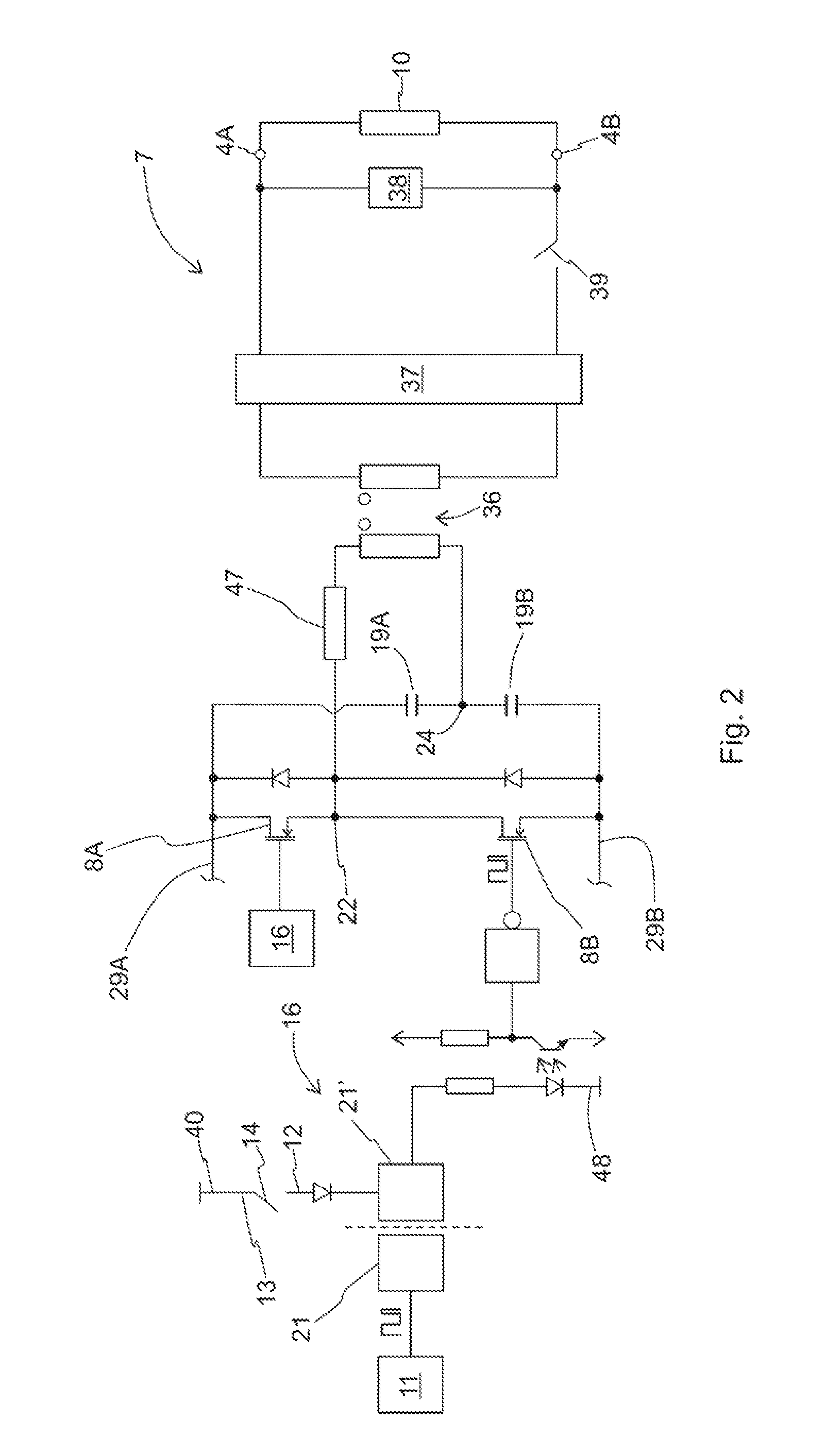
[0019]In a preferred embodiment of the invention the signal path of the control pulses from the processor to the brake switching logic is arranged via an isolator. In this context an isolator means a component that disconnects the passage of an electrical charge along a signal path. In an isolator the signal is consequently transmitted e.g. as electromagnet radiation (opto-isolator) or via a magnetic field or electrical field (digital isolator). With the use of an isolator, the passage of charge carriers from the brake control circuit to the brake switching logic is prevented e.g. when the brake control circuit fails into a short-circuit.
[0027]The invention also relates to a brake controller for controlling an electromagnetic brake of an elevator. The brake controller comprises an input for connecting the brake controller to a DC electricity source, an output for connecting the brake controller to the electromagnet of a brake, a transformer, which comprises a primary circuit and a secondary circuit, and also a rectifying bridge, which is connected between the secondary circuit of the transformer and the output of the brake controller. The input comprises a positive and a negative current conductor, and the brake controller comprises a high-side switch and a low-side switch, which are connected in series with each other between the aforementioned positive and aforementioned negative current conductor, and also a processor, with which the electricity supply to the electromagnet of the brake is controlled by producing control pulses in the control poles of the high-side switch and low-side switch. The brake controller also comprises two capacitors, which are connected in series with each other between the aforementioned positive and aforementioned negative current conductor The primary circuit of the transformer is connected between the connection point of the aforementioned high-side switch and aforementioned low-side switch and the connection point of the aforementioned capacitors. The aforementioned DC voltage source to be connected to the input is most preferably the DC intermediate circuit of the frequency converter driving the hoisting machine of the elevator. In the aforementioned circuit the voltage of the capacitors reduces the voltage over the primary circuit of the transformer, as a result of which the positive and negative current conductor in the input of the brake controller can be connected to the high-voltage DC intermediate circuit of the frequency converter without the special requirements of the transformer increasing unreasonably. The voltage of the DC intermediate circuit of the frequency converter is preferably approx. 500 V-700 V. In a preferred embodiment of the invention a separate choke is also connected between the primary circuit of the transformer and the connection point of the high-side and low-side switches. The choke reduces the current ripple of the transformer and facilitates adjustment of the current.

Problems solved by technology

Connecting a relay causes a noise, which might disturb the residents of a building.
Relays are also large in size, owing to which their placement might be awkward, especially in elevator systems that have no machine room.
As mechanical components, relays also wear rapidly and they might fail when, among other things, the contacts corrode or when they weld closed.

Method used


Image

  • Brake controller, elevator system and a method for performing an emergency stop with an elevator hoisting machine driven with a frequency converter
  • Brake controller, elevator system and a method for performing an emergency stop with an elevator hoisting machine driven with a frequency converter
  • Brake controller, elevator system and a method for performing an emergency stop with an elevator hoisting machine driven with a frequency converter

Examples


Embodiment Construction

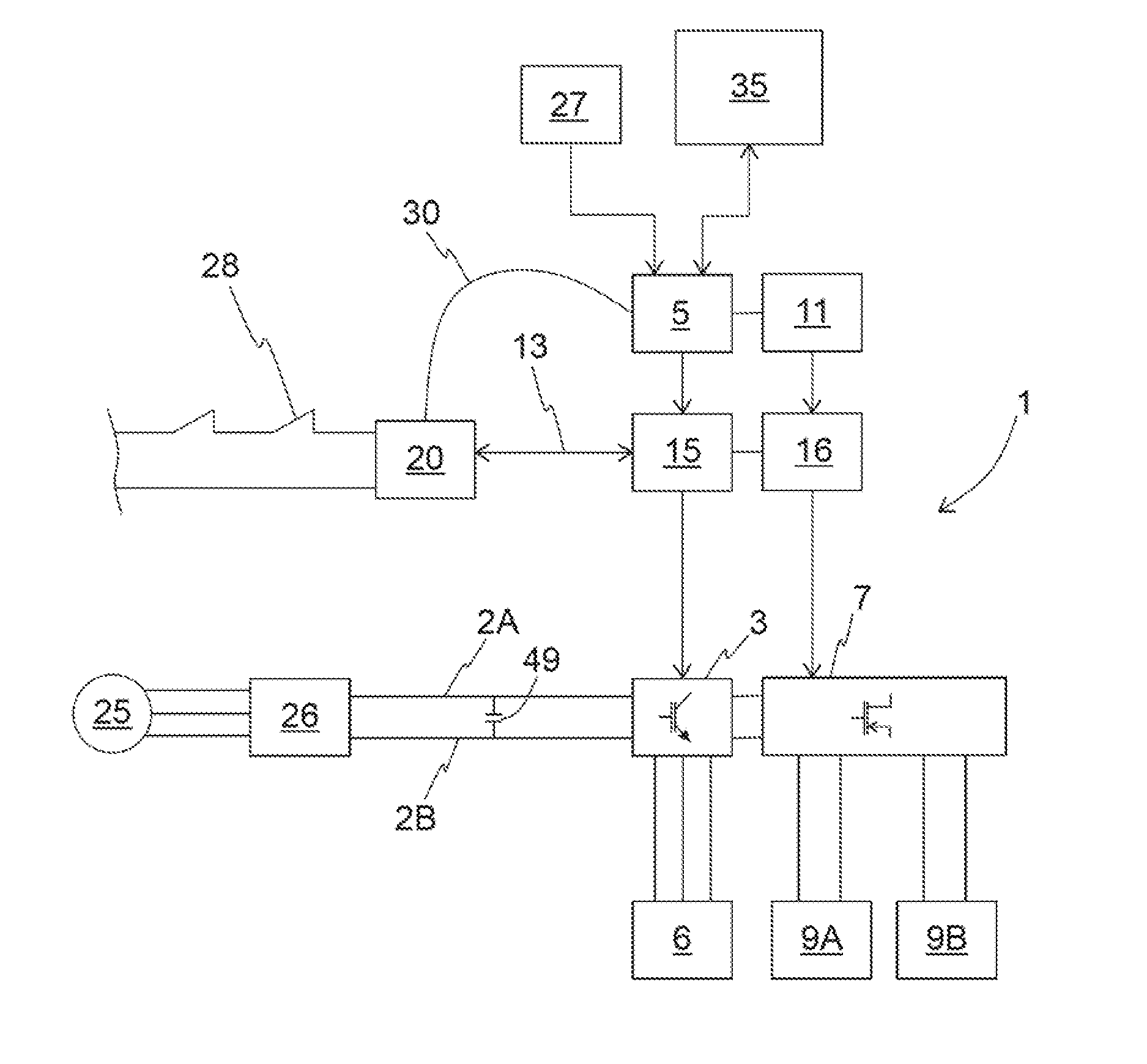
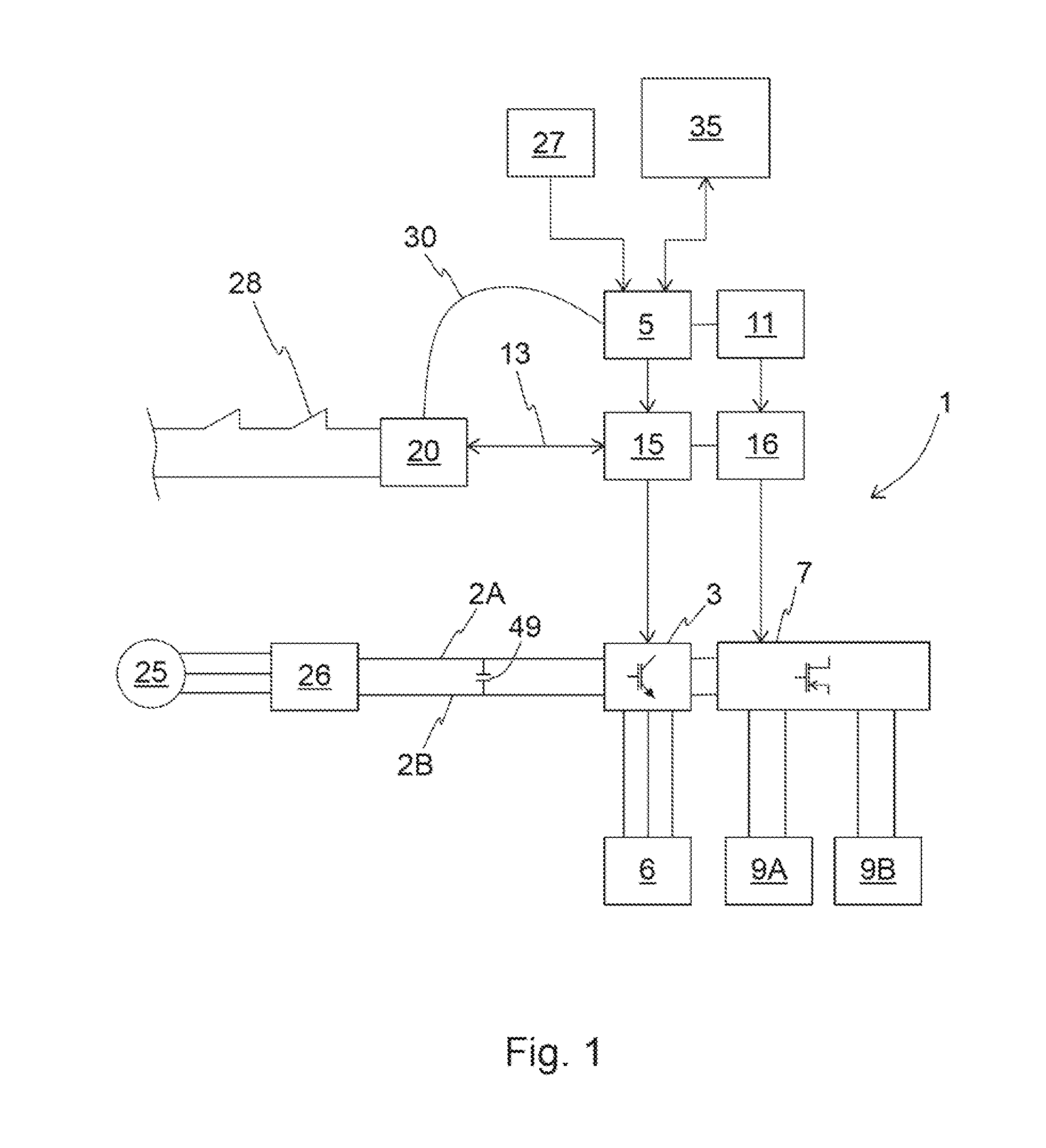
[0039]FIG. 1 presents as a block diagram an elevator system, in which an elevator car (not in figure) is driven in an elevator hoistway (not in figure) with the hoisting machine 6 of the elevator via rope friction or belt friction. The speed of the elevator car is adjusted to be according to the target value for the speed of the elevator car, i.e. the speed reference, calculated by the elevator control unit 35. The speed reference is formed in such a way that passengers can be transferred from one floor to another with the elevator car on the basis of elevator calls given by elevator passengers.

[0040]The elevator car is connected to the counterweight with ropes or with a belt traveling via the traction sheave of the hoisting machine. Various roping solutions known in the art can be used in an elevator system, and they are not presented in more detail in this context. The hoisting machine 6 also comprises an elevator motor, which is an electric motor, with which the elevator car is d...


PUM


Abstract

A brake controller, an elevator system and a method for performing an emergency stop are provided. The brake controller includes an input for connecting the brake controller to the DC intermediate circuit of the frequency converter driving the hoisting machine of the elevator, an output for connecting the brake controller to the electromagnet of the brake, a switch for supplying electric power from the DC intermediate circuit of the frequency converter driving the hoisting machine of the elevator via the output to the electromagnet of a brake, and also a processor with which the operation of the brake controller is controlled by producing control pulses in the control pole of the switch of the brake controller.

Description

FIELD OF THE INVENTION[0001]The invention relates to controllers of a brake of an elevator.BACKGROUND OF THE INVENTION[0002]In an elevator system electromagnetic brakes are used as, inter alia, holding brakes of the hoisting machine and also as car brakes, which brake the movement of the elevator car by engaging with a vertical guide rail that is in the elevator hoistway.[0003]The electromagnetic brake is opened by supplying current to the coil of the electromagnet of the brake and connected by disconnecting the current supply of the coil of the electromagnet of the brake.[0004]Conventionally, relays have been used for the current supply / disconnection of the current supply, said relays being connected in series between a power source and the coil of the electromagnet of the brake.[0005]Connecting a relay causes a noise, which might disturb the residents of a building. Relays are also large in size, owing to which their placement might be awkward, especially in elevator systems that ...

Claims


Application Information

Patent Timeline
Patent Type & Authority Applications(United States)
IPC IPC(8): B66B1/32B66B5/06B66B5/00
CPCB66B1/32B66B5/0031B66B5/06B66B5/00B66B5/025B66B5/02B66B1/30B66B2201/00B66B13/22B66B1/308
Inventor KATTAINEN, ARIRAASSINA, PASISAARIKOSKI, TAPIOSTOLT, LAURINAKARI, ARTOKALLIONIEMI, ANTTI
Owner KONE CORP
Why Eureka
Try Eureka