
Gyro drift cancelation

a gyroscope and gimbal technology, applied in the field of gyroscope calibration systems, can solve the problems of small disturbances of electro-optical sensors, such as vibration or unsteady hands, that can be easily changed, and the direction and rate are notoriously unpredictabl

Active Publication Date: 2015-01-22
DRS SUSTAINMENT SYST
View PDF2 Cites 21 Cited by
  • Summary
  • Abstract
  • Description
  • Claims
  • Application Information

AI Technical Summary

Benefits of technology

The patent describes methods, devices, and systems for correcting the drift of vehicle-mounted gyroscopes. The invention involves detecting when the vehicle is not moving and when the gimbal is not commanded to move, and using the data from the gyroscope to compensate for drift when the vehicle is moving. The invention can automatically update the drift rate as the vehicle stops and starts, and can use the rotation of the Earth to measure the drift rate and compensate for it. The technical effects of the invention include improved accuracy and stability of vehicle navigation and improved safety during vehicle movement.

Problems solved by technology

However, small disturbances to electro-optical sensors, such as vibrations or unsteady hands, are magnified when looking across long distances.
That is, they tend to sense a slight amount of rotation even when they are still, owing to imperfections in bearings, laser mirrors, etc.
Gyroscopic drift is often in one direction for awhile with a constant rate over time; however, the direction and rate are notoriously unpredictable and can change depending on external factors, such as temperature.

Method used


Image

  • Gyro drift cancelation
  • Gyro drift cancelation
  • Gyro drift cancelation

Examples


Embodiment Construction

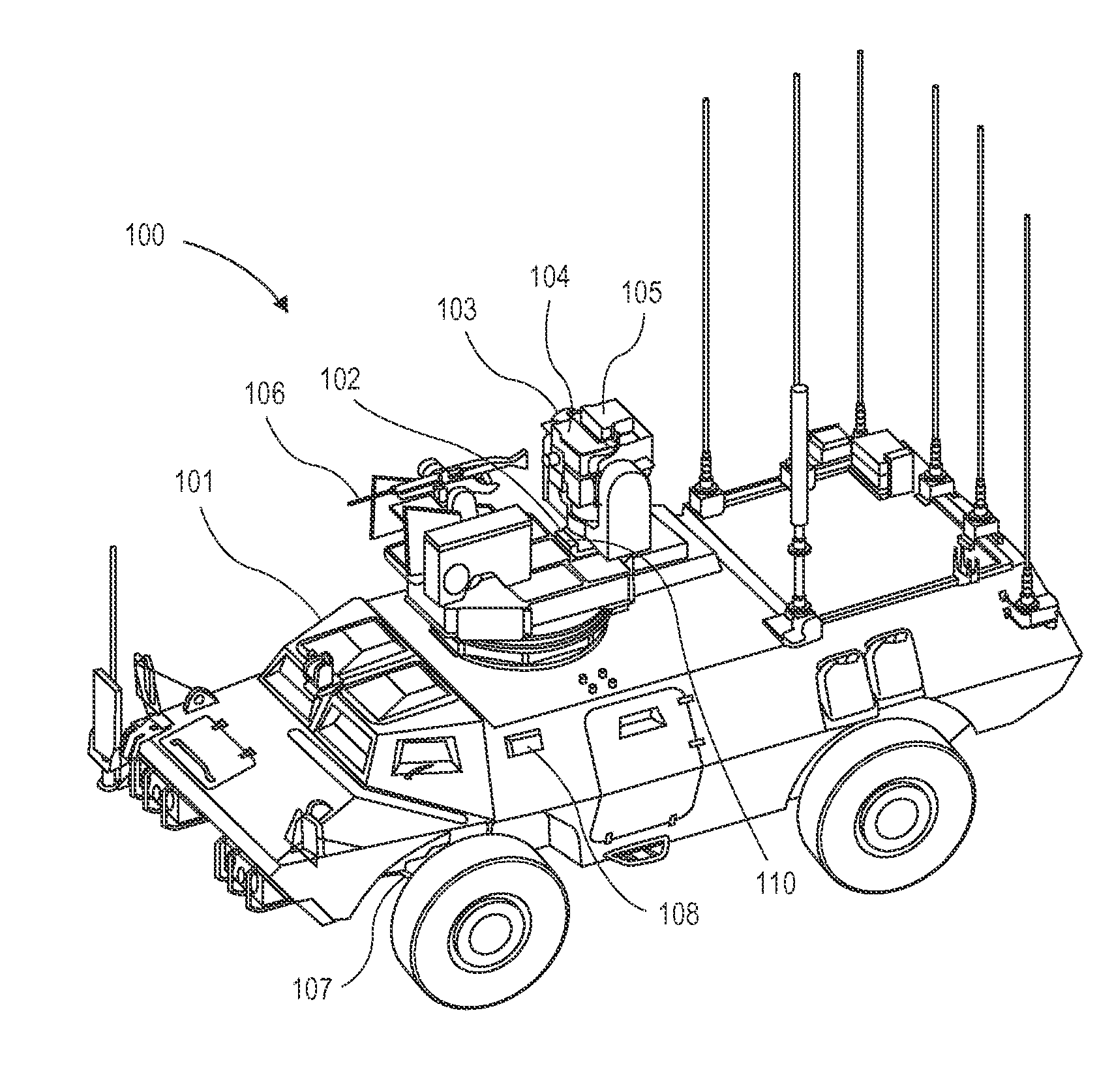
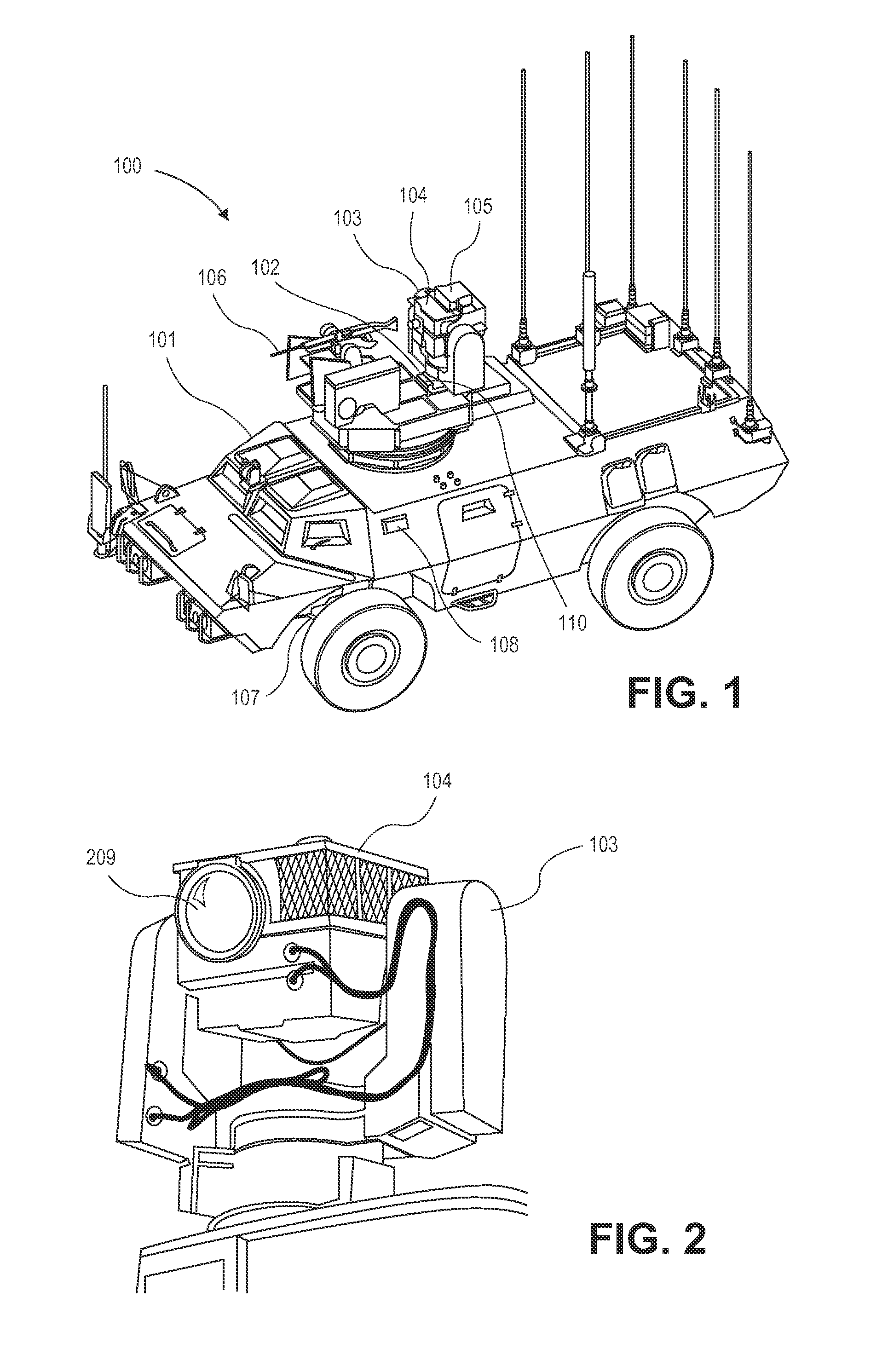
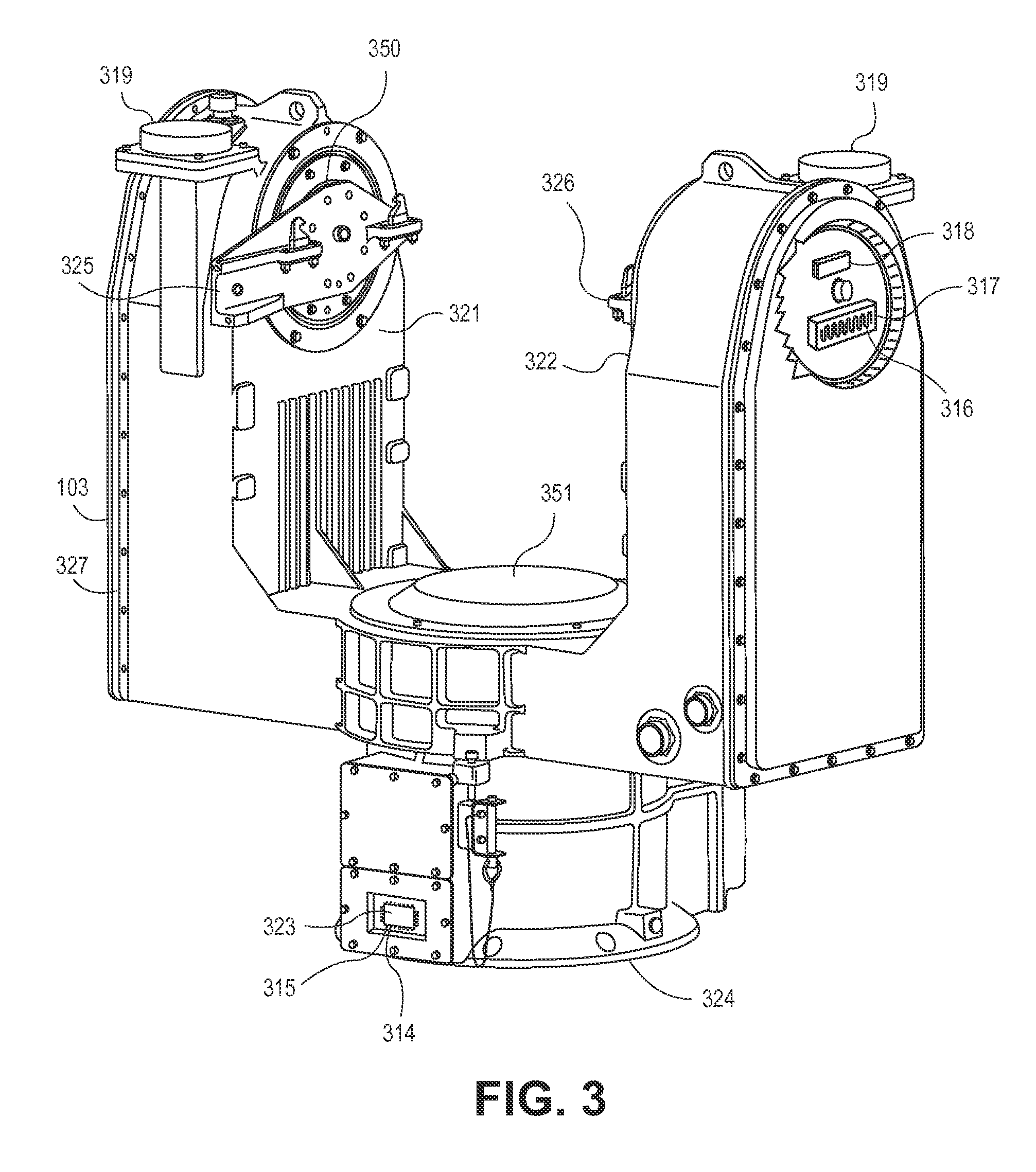
[0034]Aspects of embodiments of the presently claimed invention provide a capability of eliminating inherent drift associated with a gyro stabilized gimbal mounted to a vehicle chassis. An embodiment can utilize the measured values of vehicle motion, gimbal based acceleration, and gimbal resolver angles within the gimbal to compute a corrective factor that minimizes the effects of gyro drift on the stabilization performance of the gimbal system.

[0035]An accelerometer triad in the base of the gimbal can be used to detect gimbal platform motion. A vehicle motion sensor (VMS) can be combined with accelerometer data to form a more robust assessment of gimbal base motion. If both the vehicle motion sensor and accelerometer indicate no movement, then it can reasonably be inferred that any rotation detected by the gyroscope and used to stabilize the gimbal by rotating the gimbal's azimuth or elevation motors is due to gyroscope drift.

[0036]Rotation-indicating data caused by the gyroscope c...


PUM


Abstract

Methods, devices, and systems are presented for compensating for gyroscopic drift in a stabilized gimbal system mounted on a vehicle. When the vehicle is parked and the gimbal is not being commanded to move by an operator, encoders or resolvers of the gimbal stabilized system are read and periodically read thereafter. When the vehicle begins to move or the gimbal is commanded to move, the last periodic reading of the resolvers is used to determine the amount that the gimbal has moved during the rest period. A gyroscopic drift rate is computed by dividing the amount of angular movement by the time period between the readings, and the gyroscopic drift rate is used for corrections while the vehicle is moving or gimbal is commanded to move. Each time the vehicle stops, the gyroscopic drift rate is re-computed and updated. The gyroscope can be heated until the drift rate is constant with respect to temperature, further helping the calibration.

Description

CROSS-REFERENCES TO RELATED APPLICATIONS[0001]NOT APPLICABLESTATEMENT AS TO RIGHTS TO INVENTIONS MADE UNDER FEDERALLY SPONSORED RESEARCH AND DEVELOPMENT[0002]NOT APPLICABLECOPYRIGHT[0003]A portion of the disclosure of this patent document contains material which is subject to copyright protection. The copyright owner has no objection to the facsimile reproduction by anyone of the patent document or the patent disclosure, as it appears in the Patent and Trademark Office patent file or records, but otherwise reserves all copyright rights whatsoever.BACKGROUND[0004]1. Field of the Art[0005]This disclosure is generally related to instrument calibration systems for gyroscopes, and more specifically to correction of gyroscopic drift for gimbal-stabilized platforms mounted on military-grade and other vehicles.[0006]2. Background[0007]Modern warfare has evolved to value precision weapons, which typically limit collatoral damage while reducing ordinance mass required to be delivered to the f...

Claims


Application Information

Patent Timeline
IPC IPC(8): G01C19/04
CPCG01C19/04G01C19/00G01C25/005
Inventor LINTON, THOMAS D.FOX, MICHAEL T.EXELY, BRUCE E.
Owner DRS SUSTAINMENT SYST
Learn More