Device for 3D display of photo finish image

Active Publication Date: 2015-01-15
SWISS TIMING
View PDF5 Cites 5 Cited by
  • Summary
  • Abstract
  • Description
  • Claims
  • Application Information

AI Technical Summary

Benefits of technology

The present invention provides a simple way to create a photo finish image in relief, without complex tools, and can be easily displayed to spectators or TV viewers. Additionally, the invention offers a modular architecture for implementing a stereoscopic display system that requires minimal modifications to existing infrastructures for photo finish systems.

Problems solved by technology

It may happen however that the resolution of the timing system, for example typically a hundredth of a second, is insufficient to distinguish between two competitors whose measured time is identical.
However, because of the precise alignment required on the finish line, none of the cameras used can be shifted laterally to resolve this masking problem; this is why the two cameras employed are respectively located on either side of the finish line.
However, these optical systems are unfortunately unsuitable for a photo finish system because of the lateral offset that is required between the photograph shooting axes, which cannot be simultaneously aligned on the finish line and therefore there is no possibility of these systems overcoming the shortcomings of the timing system in a reliable and accurate manner.

Method used


Image

  • Device for 3D display of photo finish image
  • Device for 3D display of photo finish image
  • Device for 3D display of photo finish image

Examples


Embodiment Construction

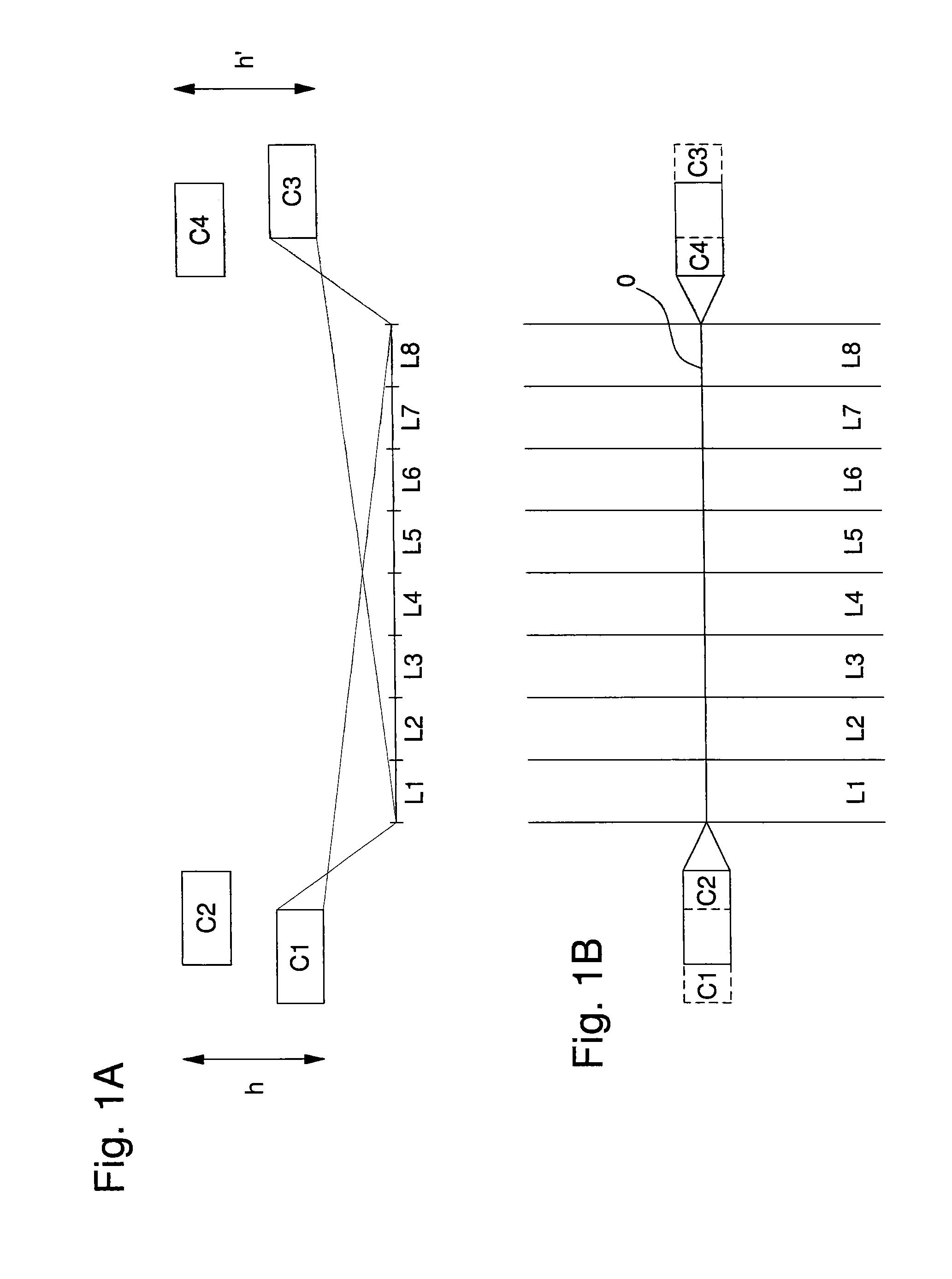
[0018]FIG. 1A shows a front view, in the axis of a finish line, of a plurality of cameras used in a preferred embodiment of the present invention. This Figure shows the various lanes L1, L2, L3, L4, L5, L6, L7, L8, which are the normal lanes of an athletics track, and four cameras C1, C2, C3, C4 arranged at a height on each side of the athletics track. According to this preferred embodiment, the stereoscopic images are formed from two images taken at the same reference moment by both cameras which are offset vertically from each other. Thus a first camera C1 and a second camera C2, both aligned on the finish line, are offset from each other by a first height h and similarly a third camera C3 and a fourth camera C4, both aligned on the finish line, are offset from each other by a second height h′. The advantage of arranging two pairs of cameras located on either side of the finish line, i.e. in forming pairs C1-C2 and C3-C4, consists in the ability to choose the most advantageous cam...


PUM


Abstract

An imaging device for a photo finish system, including a first camera aligned on a finish line and a mechanism for display of three dimensional stereoscopic images.

Description

FIELD OF THE INVENTION[0001]The present invention concerns the display of timed data during a sports competition, and more specifically a photo finish type at a finish line.BACKGROUND OF THE INVENTION[0002]In timed sports races or competitions, and in particular athletics races, the timing device is generally started in a synchronised manner with the emission of an acoustic signal, and stopped for each competitor when each competitor respectively crosses the finish line. It may happen however that the resolution of the timing system, for example typically a hundredth of a second, is insufficient to distinguish between two competitors whose measured time is identical. To achieve this, auxiliary devices are required to assist timing and there are manually operated systems for this purpose which are based on the visual recognition of images taken in sequence by a high definition camera very precisely centred on the finish line. An operator analyses, in an asynchronous manner after the ...

Claims


Application Information

Patent Timeline
IPC IPC(8): H04N13/02H04N7/18G03B41/00H04N7/08
CPCH04N7/0806H04N7/181G03B41/00H04N13/0242G03B15/00G03B17/24G03B35/08G07C1/24G04F10/00H04N13/243
Inventor RICHARD, PASCAL
Owner SWISS TIMING
Why Eureka
Try Eureka