
Optical Anti-Shake Apparatus with Switchable Light Path

a light path and anti-shake technology, applied in the field of optical anti-shake apparatuses with switchable light paths, can solve problems such as inability to image capture modules, and achieve the effect of reducing the number of optical anti-shake devices

Active Publication Date: 2015-01-01
TDK TAIWAN
View PDF8 Cites 151 Cited by
  • Summary
  • Abstract
  • Description
  • Claims
  • Application Information

AI Technical Summary

Benefits of technology

The present invention is about an optical device with a function to prevent shaking during image capture. The device has a switchable light path that is used to direct the light from outside sources onto the optical system. There are two different light paths, and the anti-shake device can switch between them to ensure that the light is directed towards the image capturing module. This results in higher quality photos and videos.

Problems solved by technology

In an optical system consisted of an optical lens set and an image capturing module, such as a camera, a video recorder and so on, unexpected foreign forcing or hand shake of the camera and / or the video recorder may offset the light path so as to cause unstable imaging on the image capturing module.

Method used


Image

  • Optical Anti-Shake Apparatus with Switchable Light Path
  • Optical Anti-Shake Apparatus with Switchable Light Path
  • Optical Anti-Shake Apparatus with Switchable Light Path

Examples


Embodiment Construction

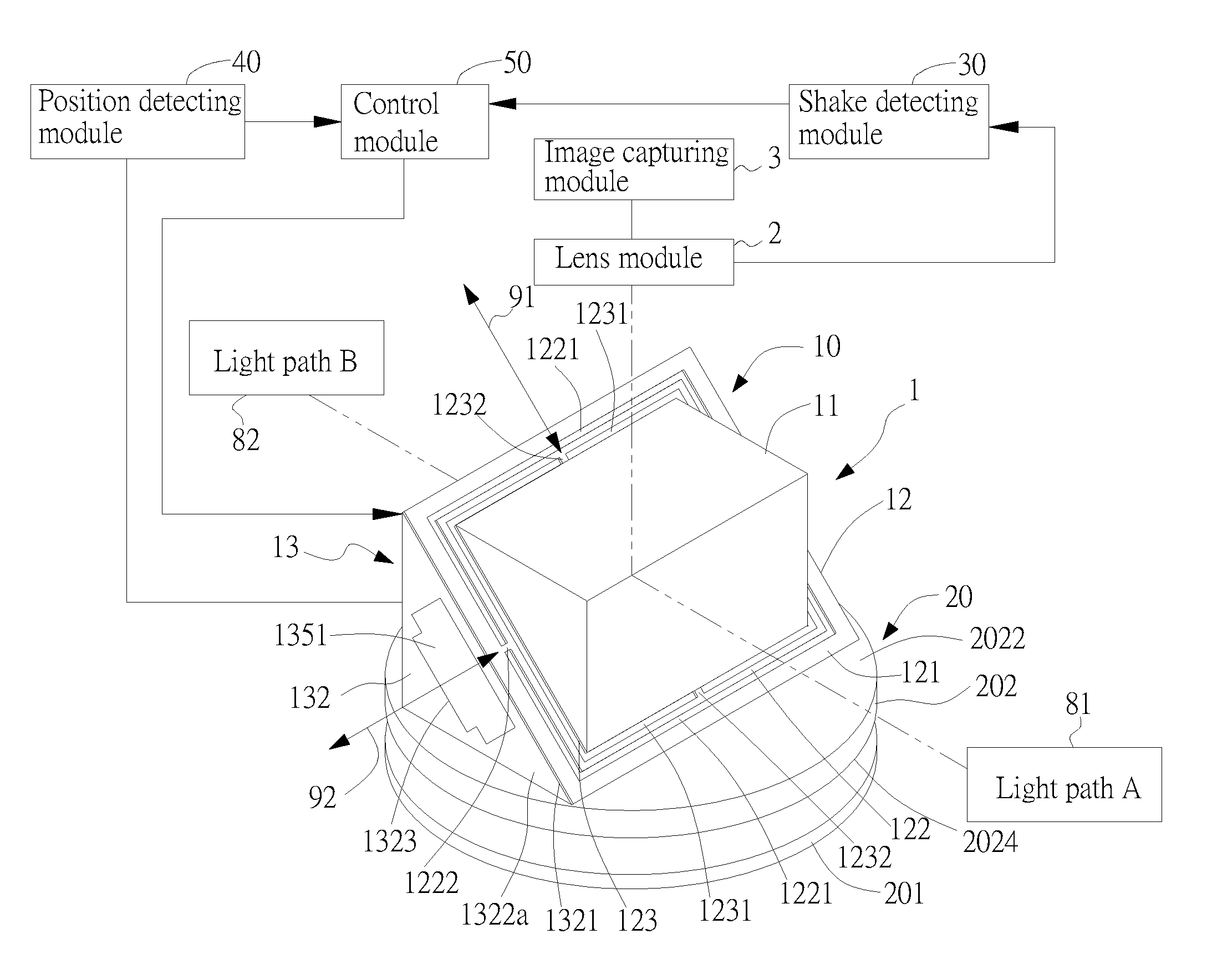
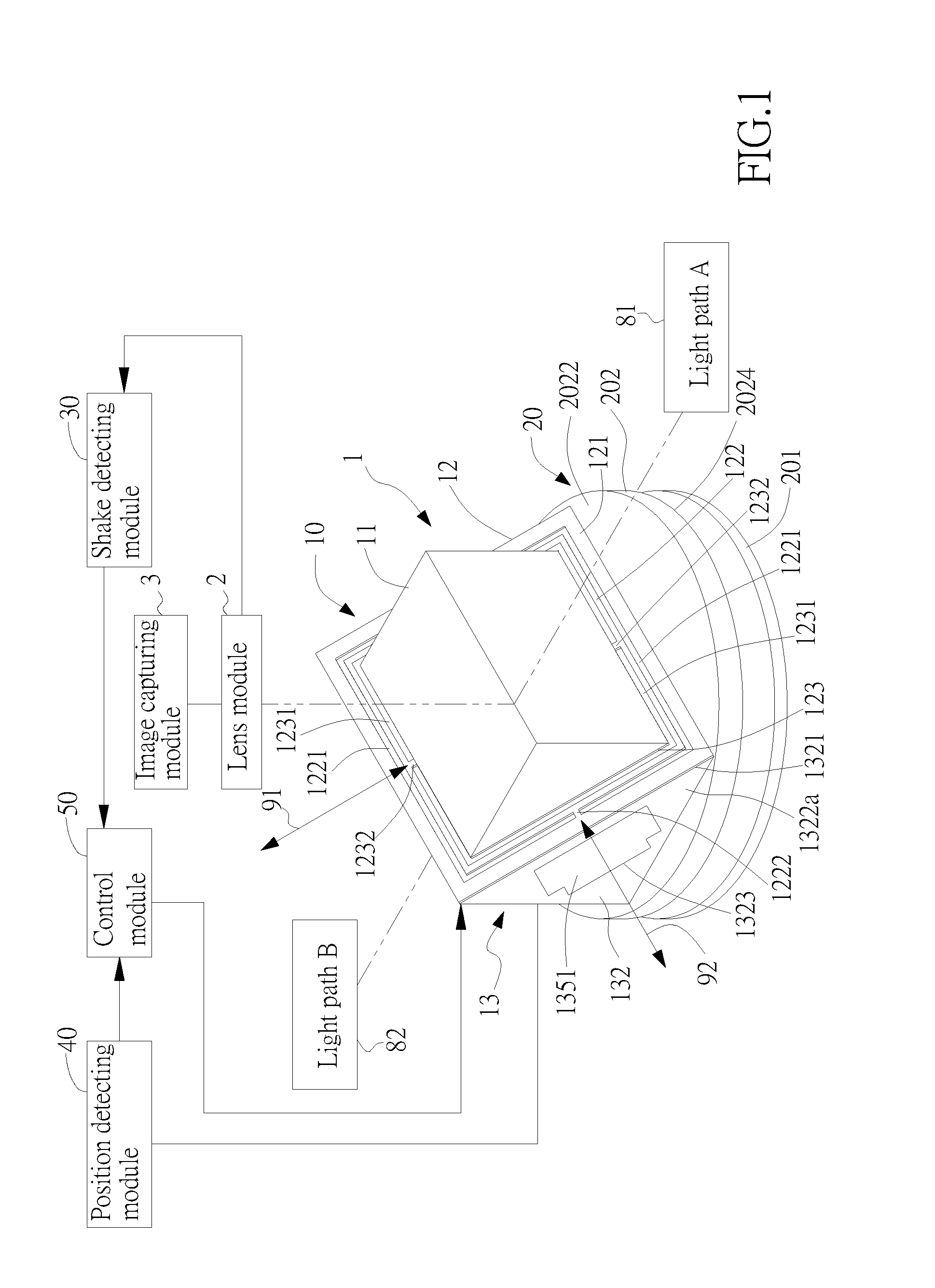
[0026]The invention disclosed herein is directed to an optical anti-shake apparatus with a switchable light path. In the following description, numerous details are set forth in order to provide a thorough understanding of the present invention. It will be appreciated by one skilled in the art that variations of these specific details are possible while still achieving the results of the present invention. In other instance, well-known components are not described in detail in order not to unnecessarily obscure the present invention.

[0027]In the present invention, the optical anti-shake apparatus with a switchable light path is mainly mounted in an optical system. The optical system further includes two different light inlet windows for allowing outside lights to be projected therethrough onto the optical system. The incident lights through the corresponding light inlet windows are characterized into defining respectively at least two different light paths with corresponding light i...


PUM


Abstract

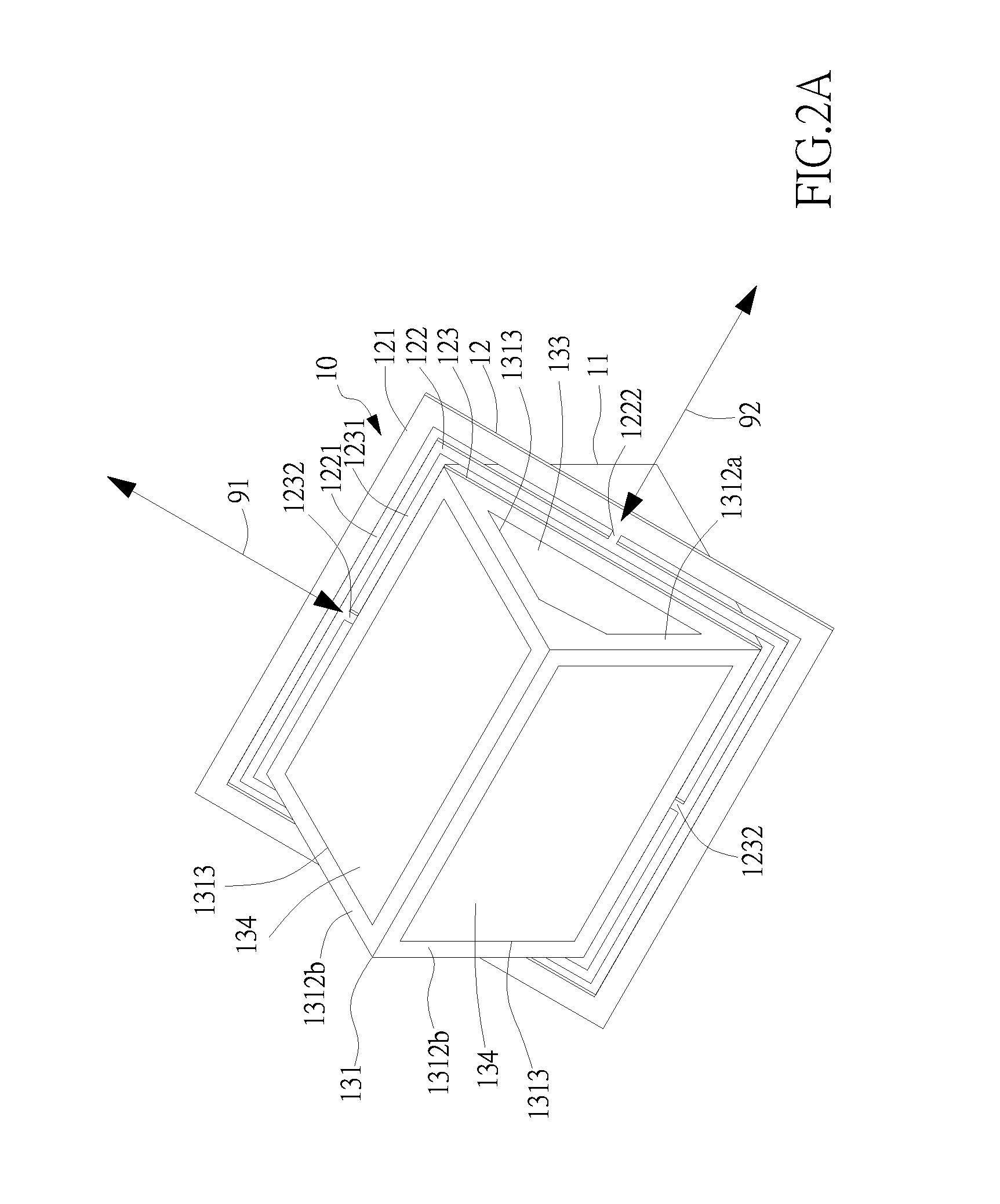
An optical anti-shake apparatus with a switchable light path is furnished in an optical system having two light paths of different directions. The optical system also comprises a lens module, an image capturing module, an anti-shake device and a switching device. The lens module corresponds to the image capturing module in position. The switching device comprises a fixing member, a rotary member and a driving module. The rotary member is pivotal about the fixing member. The driving module is located between the rotary member and the fixing member. The anti-shake device is located on the rotary member such that the driving module can drive and rotate the rotary member together with the anti-shake device in order to perform switching operations, and thereby the light of either of the two light paths can be directed toward the lens module so as to focus at the image capturing module.

Description

[0001]This application claims the benefit of Taiwan Patent Application Serial No. 102123439, filed Jul. 1, 2013, the subject matter of which is incorporated herein by reference.BACKGROUND OF INVENTION[0002]1. Field of the Invention[0003]The invention relates to an optical anti-shake apparatus with a switchable light path, and more particularly to the apparatus that applies a switching device to drive an anti-shake device for performing switching operations so as to project one of two light paths onto an image capturing module via a lens module.[0004]2. Description of the Prior Art[0005]In an optical system consisted of an optical lens set and an image capturing module, such as a camera, a video recorder and so on, unexpected foreign forcing or hand shake of the camera and / or the video recorder may offset the light path so as to cause unstable imaging on the image capturing module. Namely, obscure images can hence be generated. One of many resorts in the art to resolve the aforesaid ...

Claims


Application Information

Patent Timeline
IPC IPC(8): G02B26/08H04N5/232
CPCH04N5/2328G02B26/085H04N5/23258H04N5/2259G03B5/00H04N23/685G02B26/0816G02B27/646G03B17/17G03B2205/0023H04N23/58H04N23/6812
Inventor HU, CHAO CHANGWENG, CHIH WEI
Owner TDK TAIWAN
Learn More