Pressurization Device

a technology for pressurizing devices and substances, which is applied in the direction of non-fuel substance addition to fuel, containers, pliable tubular containers, etc., can solve the problems of inconsistent quantities of fuel and lubricant in the fuel-lubricant mixture, and the inability to merely compress the second substan

Inactive Publication Date: 2014-12-04
PERKINS ENGINES
View PDF1 Cites 4 Cited by
  • Summary
  • Abstract
  • Description
  • Claims
  • Application Information

AI Technical Summary

Benefits of technology

This patent describes an additive container that connects to a pressurization device for dispensing additives. The container has a flexible bladder for holding additive and a support member for attaching it to the pressurization device. The bladder outlet is connected to the additive outlet passage. The pressurization device also includes a first housing with a fluid inlet passage and an additive outlet passage, and a second housing that detachably mounts to the first housing and creates a chamber in fluid communication with the fluid inlet passage. The additive container is placed in this chamber and has an additive flow passage in fluid communication with the additive outlet passage. The technical effect is a convenient and easy way to connect a pressurization device to an additive container for dispensing additives.

Problems solved by technology

That is to say, it may not be appropriate merely to compress the second substance to a set pressure because the first substance may not be at a constant pressure.
However, some smaller, mobile installations exist where available space and energy for pressurizing the second substance are rather limited and thus a significant concern.
However, those systems store the fuel-lubricant mixture in the tank ready for consumption and the substances are known to separate when left for some time or as they are drawn from the tank.
This leads to fuel-lubricant mixtures having inconsistent quantities of fuel and lubricant.

Method used


Image

  • Pressurization Device
  • Pressurization Device
  • Pressurization Device

Examples


Embodiment Construction

[0027]The following is a detailed description of an exemplary embodiment of the present disclosure. The exemplary embodiment described therein and illustrated in the drawings is intended to teach the principles of the present disclosure, enabling those of ordinary skill in the art to implement and use the present disclosure in many different environments and for many different applications. Therefore, the exemplary embodiment is not intended to be, and should not be considered as, a limiting description of the scope of patent protection. Rather, the scope of patent protection shall be defined by the appended claims.

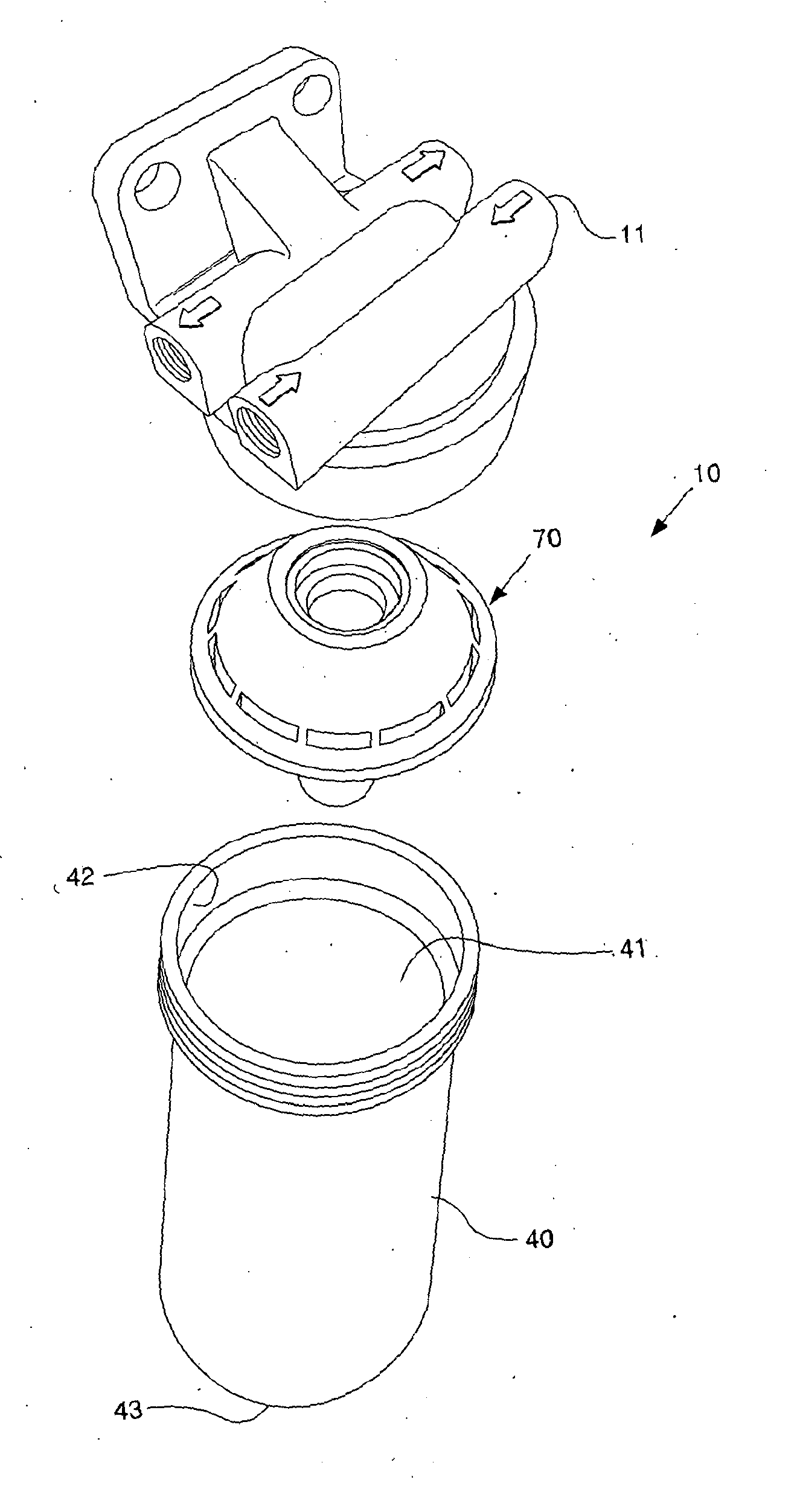
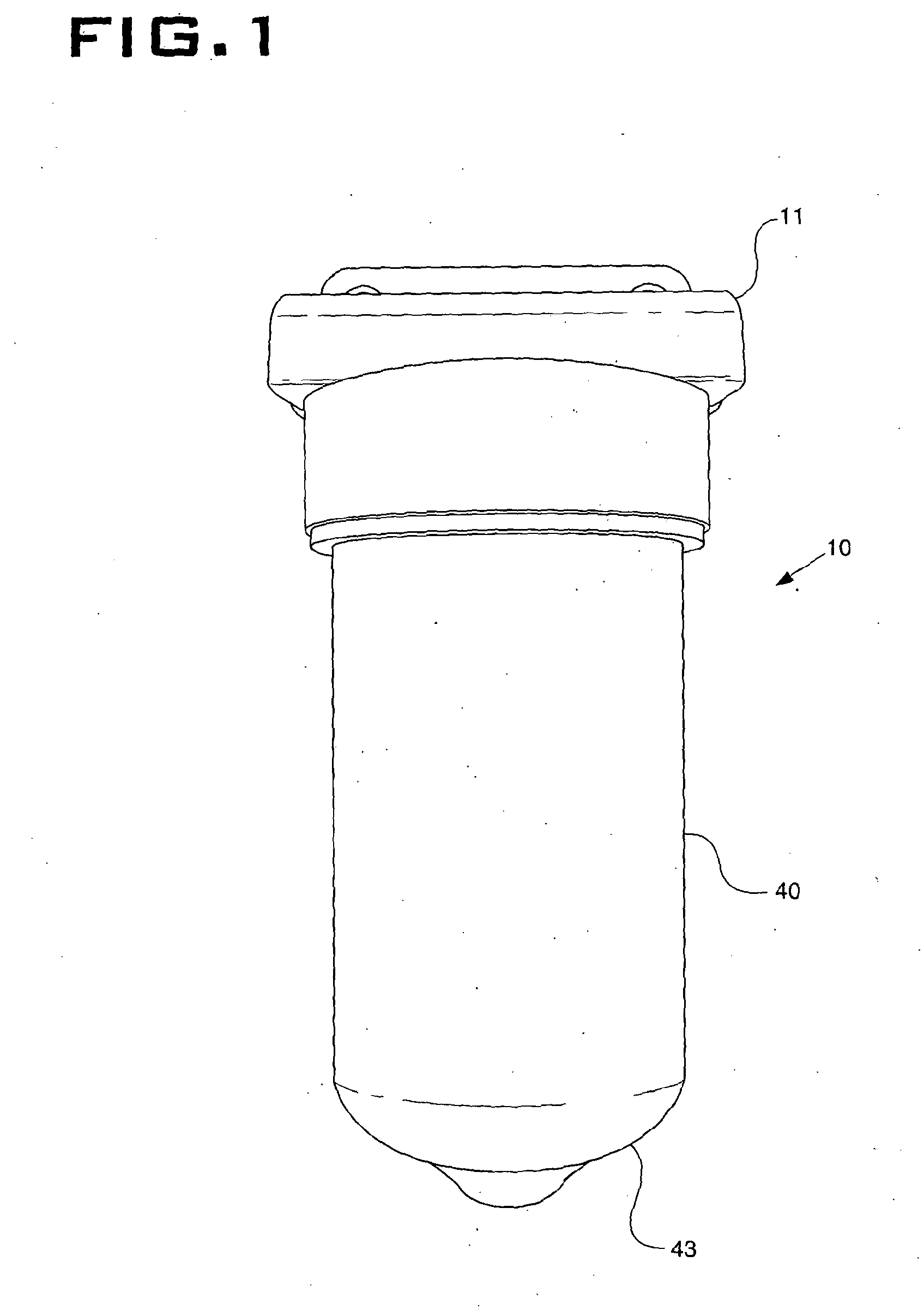
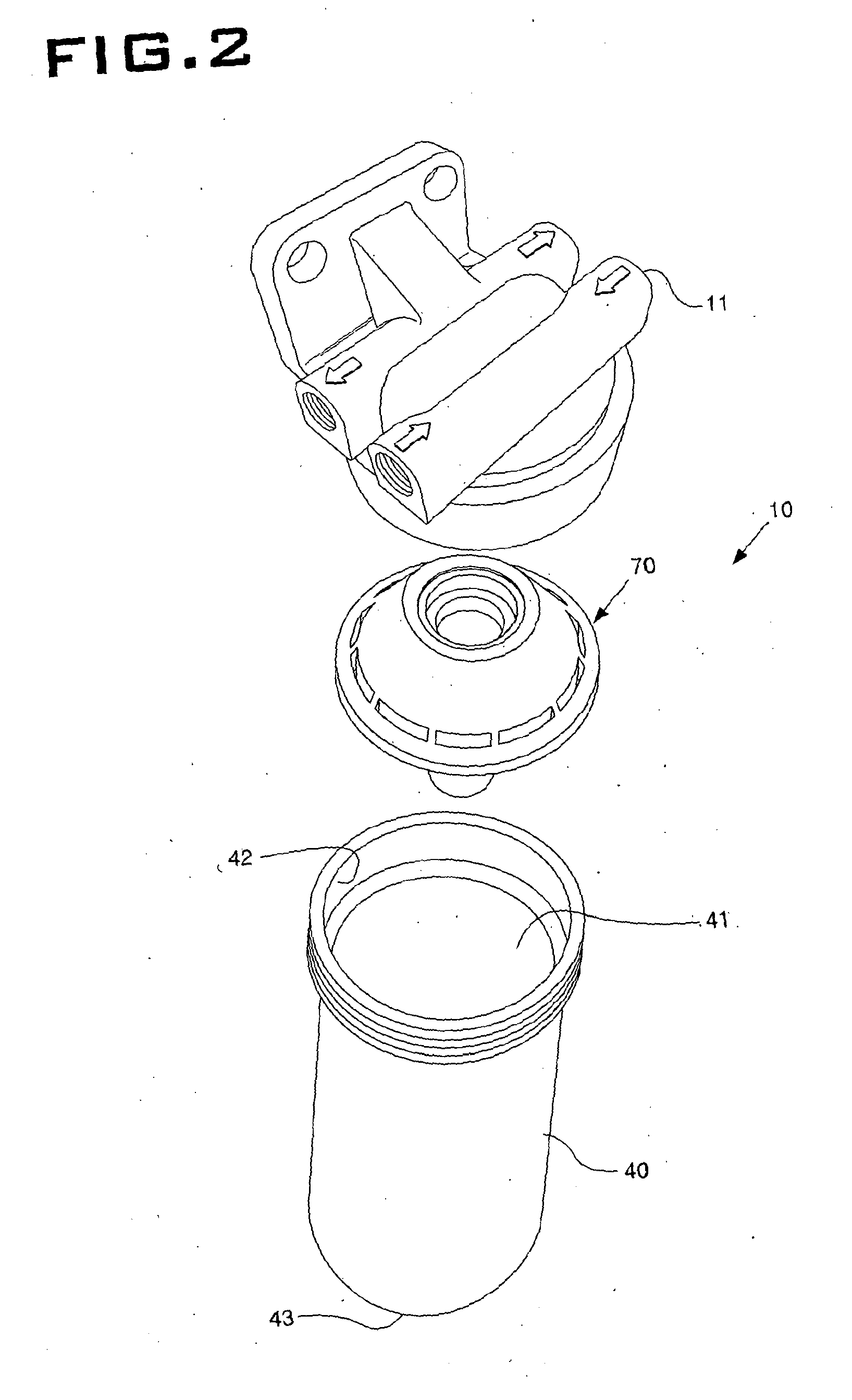
[0028]Referring to FIGS. 1 to 3, there is shown a device, generally indicated 10, for pressurizing a substance (not shown). The device 10 may be used for pressurizing a first substance contained in the device 10 to a pressure corresponding substantially to that of another substance. The device 10 is configured to pressurize a liquid substance, though it may also be suited...


PUM


Abstract

The present disclosure relates to an apparatus (10) for pressurizing a first substance, such as a liquid, gas or particulate material, to a pressure substantially equal or similar to the pressure of a second substance, i.e. a reference substance. The pressure of the reference substance may be transient so the pressure of the first substance must be varied accordingly. The present disclosure includes a bladder (71) disposed within a sealed can (40), an inlet passage (24a) in communication with the interior (41) of the can and an outlet passage (26a) in communication with the interior of bladder (71). The reference substance may be directed into the interior (41) of the can (40) via the inlet passage (24a) and pressurizes the bladder (71) and thus the first substance stored therein, thereby causing the first substance to be expelled via the outlet passage (26a) with a pressure substantially corresponding to that of the reference substance. Many applications exist that require two substances to be of a similar pressure. For example, an engine may be adapted to run on low lubricity fuel provided a pressurized lubricant is introduced to the pressurized fuel before being directed towards the injector.

Description

TECHNICAL FIELD[0001]The present disclosure relates to a device for pressurizing a substance and more particularly to a device for pressurizing a substance to a pressure substantially equal or similar to that of another substance. The present disclosure also relates to component parts for such a device.BACKGROUND[0002]Some installations use or consume various substances, including gases, liquids or particulates. Furthermore, those installations may require some of those substances to be at a particular pressure, and sometimes at a pressure substantially equal or similar to that of another substance. This requirement may be for various reasons, including the possibility of subsequently combining controlled quantities of first and second substances to create a composition of specific proportions of each substance. The effective control of those quantities may be improved when the first and second substances are at substantially the same pressure. The first and second substances may co...

Claims


Application Information

Patent Timeline
Patent Type & Authority Applications(United States)
IPC IPC(8): F02M25/06B67D7/02B67D7/72B67D7/04
CPCF02M25/06B67D7/72B67D7/0294B67D7/0478G05D16/06G05D16/028Y02T10/12
Inventor SMITH, PAUL J.
Owner PERKINS ENGINES
Why Eureka
Try Eureka