Control device for internal combustion engine

a control device and internal combustion engine technology, applied in combustion engines, electrical control, ignition circuit layouts, etc., can solve the problems of large load, difficult to supply sufficient power to the microprocessor and load to be controlled, and high setting, so as to achieve no effect on ignition operation

Active Publication Date: 2014-10-30
MAHLE INT GMBH
View PDF0 Cites 15 Cited by
  • Summary
  • Abstract
  • Description
  • Claims
  • Application Information

AI Technical Summary

Benefits of technology

[0027]According to the present invention, there is provided a power source electricity storage element that, during the exhaust stroke of the internal combustion engine, is charged by the half wave voltage generated by the ignition device-driving magneto coil for the purpose of presenting ignition energy to the ignition device; and the power source circuit is constituted such that power source voltage for presentation to the microprocessor and power source voltage for presentation to a load other than the ignition device are generated from the energy stored in this power source electricity storage element, whereby excess power can be effectively drawn from the ignition device-driving magneto coil provided to the generator installed in the internal combustion engine, and power can be supplied to the microprocessor and the load other than the ignition device, doing so with no effect on ignition operations.

Problems solved by technology

However, in a case in which, for the purpose of cost reduction or of smaller size / lighter weight of the engine, the generator attached to the engine is provided only with an ignition device-driving magneto coil, or in a case in which, despite being provided with an additional magneto coil, the additional magneto coil has a large load so as to produce no surplus output, it has sometimes proved difficult to supply sufficient power to the microprocessor and the load to be controlled.
While it would be conceivable for the first half wave voltage and the third half wave voltage of identical polarity which are output before and after the second half wave voltage (the voltage for driving the ignition device) by the external magnet type magnet generator, to be utilized as voltages for driving a load besides the ignition device, for reasons having to do with the structure of the rotor, the crest values of the first half wave voltage and the third half wave voltage cannot be set very high, and therefore it is difficult using only these voltages to supply sufficient power to a microprocessor and a load to be controlled.
Additionally, while it would be conceivable to utilize the second half wave voltage, which is employed for operating the ignition device, to supply power to a microprocessor and a load to be controlled, in a case in which such a constitution is adopted, there is insufficient energy to drive the ignition device, thereby making a decline in ignition performance unavoidable.

Method used


Image

  • Control device for internal combustion engine
  • Control device for internal combustion engine
  • Control device for internal combustion engine

Examples


Embodiment Construction

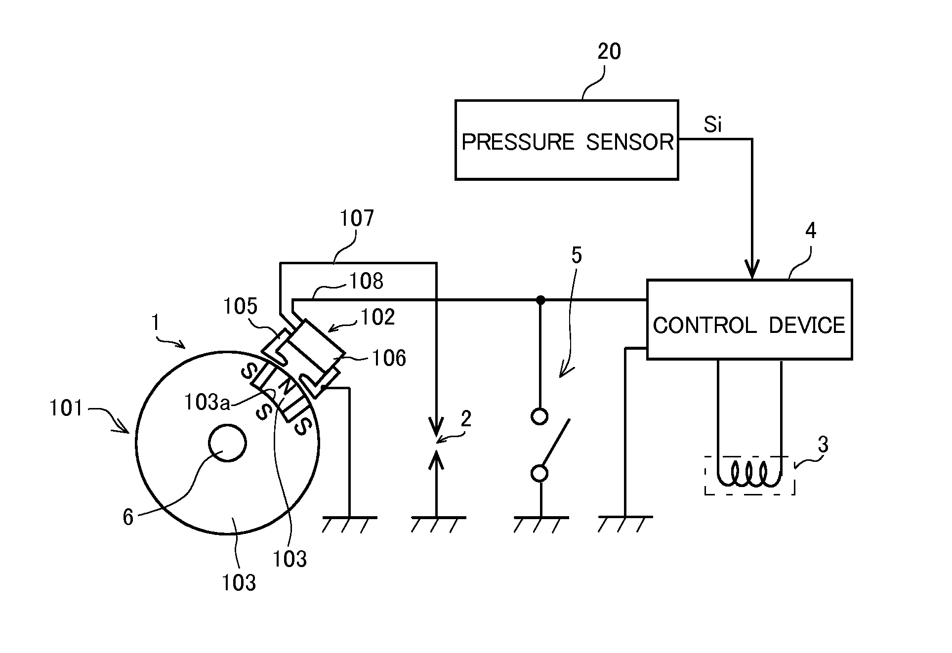
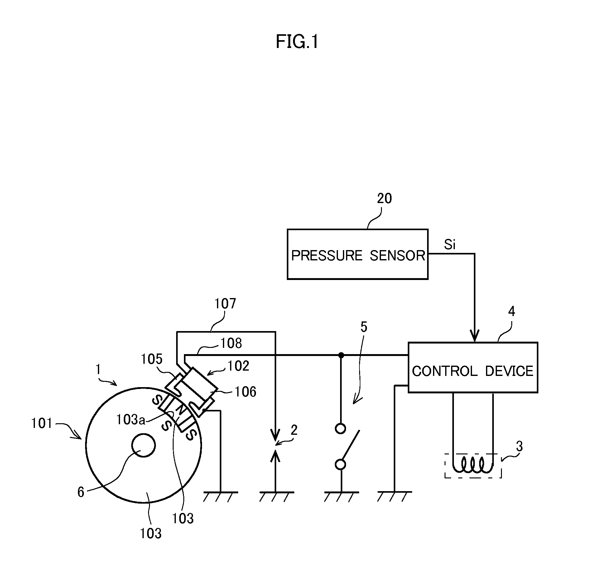
[0035]Referring to FIG. 1, there is shown in simplified form the overall constitution of an embodiment of the present invention. In FIG. 1, 1 denotes an external magnet type magnet generator driven by an internal combustion engine; 2 denotes a spark plug mounted in a cylinder of the internal combustion engine; 3 denotes a load to be controlled; 4 denotes the control device for an internal combustion engine according to the present invention (hereinafter termed simply “control device”), and 5 denotes a stop switch which is switched to the ON state when halting the internal combustion engine. 20 denotes a pressure sensor for detecting internal pressure of the intake pipe of the internal combustion engine, and for outputting a pressure detection signal Si showing the internal pressure of the intake pipe. Alternating current voltage V1 output by the magnet generator and the pressure detection signal Si output by the pressure sensor 20 are input to the control device 4.

[0036]The external...


PUM


Abstract

Provided is a control device for an internal combustion engine, employing a microprocessor to control a load other than an ignition device, the control device being provided to an internal combustion engine in which is installed a magnet generator that has a magneto coil for successively generating, in association with revolution of the internal combustion engine, a first half wave voltage, a second half wave voltage of different polarity than the first half wave voltage, and a third half wave voltage of identical polarity to the first half wave voltage; and the magnet generator employing the second half wave voltage to drive the ignition device. The device is provided with an electricity storage element which draws excess power from the output that is output by the magnet generator for the purpose of driving the ignition device, and which is charged by the first and second half wave voltages, as well as being charged by the second half wave voltage as well at times that the internal combustion engine is in the exhaust stroke, in order to supply power to the load and to the microprocessor. The power source circuit is constituted to use the energy stored in this electricity storage element to generate power source voltage for presentation to the microprocessor and to the load other than an ignition device.

Description

TECHNICAL FIELD[0001]The present invention relates to a control device for an internal combustion engine, the device using a microprocessor to control components to be controlled in the internal combustion engine.BACKGROUND ART[0002]In many instances, an internal combustion engine installed in a machine, such as a vehicle, ship, farming equipment, motor generator, or the like, is provided with a control device that uses a microprocessor to control particular components, such as machinery, belonging to the internal combustion engine. In a control device of this kind, a power source is necessary for operation of the microprocessor. Moreover, in cases in which a component to be controlled lacks a power source, it is necessary to supply a power source to the component to be controlled. Furthermore, in some cases, power is necessary for the operation of sensors as well.[0003]In a case in which the generator attached to an internal combustion engine is a magnet generator of internal magne...

Claims


Application Information

Patent Timeline
Patent Type & Authority Applications(United States)
IPC IPC(8): F02P23/04
CPCF02P23/04F02D41/0097F02P1/08F02P7/067F02D2400/14F02D2400/06
Inventor KAWAGOE, JUNSUZUKI, HIDETOSHIHIRAMATSU, KEI
Owner MAHLE INT GMBH
Why Eureka
Try Eureka