
Method and LCD Control Circuit for Driving LCD

a control circuit and liquid crystal display technology, applied in the field of electronic devices, can solve the problems of affecting the miniaturization demand of devices, affecting the miniaturization of devices, and affecting the user's health, so as to simplify the circuit design, save product costs, and simplify the effect of circuit design

Inactive Publication Date: 2014-09-25
SHENZHEN CHINA STAR OPTOELECTRONICS TECH CO LTD
View PDF5 Cites 4 Cited by
  • Summary
  • Abstract
  • Description
  • Claims
  • Application Information

AI Technical Summary

Benefits of technology

The present invention provides a method for driving an LCD with a timing controller that integrates an EEPROM to simplify circuit design and reduce costs. The method uses a display control unit to generate vertical synchronous signals and a main board system end generates 3D_EN signals, which simplifies circuit design, saves costs, and raises product integration. The LCD control circuit according to the present invention, which simplifies circuit design and saves costs, is capable of miniaturizing products and raising market competition.

Problems solved by technology

Such displays have faults such as bulk, heavy power consumption, and radiation to harm users' health.
In hence, it is difficult to meet the miniaturization demand for devices in the present on account of complicated circuit structure and cost.

Method used


Image

  • Method and LCD Control Circuit for Driving LCD
  • Method and LCD Control Circuit for Driving LCD
  • Method and LCD Control Circuit for Driving LCD

Examples


Embodiment Construction

[0038]The drawings illustrate embodiments of the invention and, together with the description, serve to explain the principles of the invention.

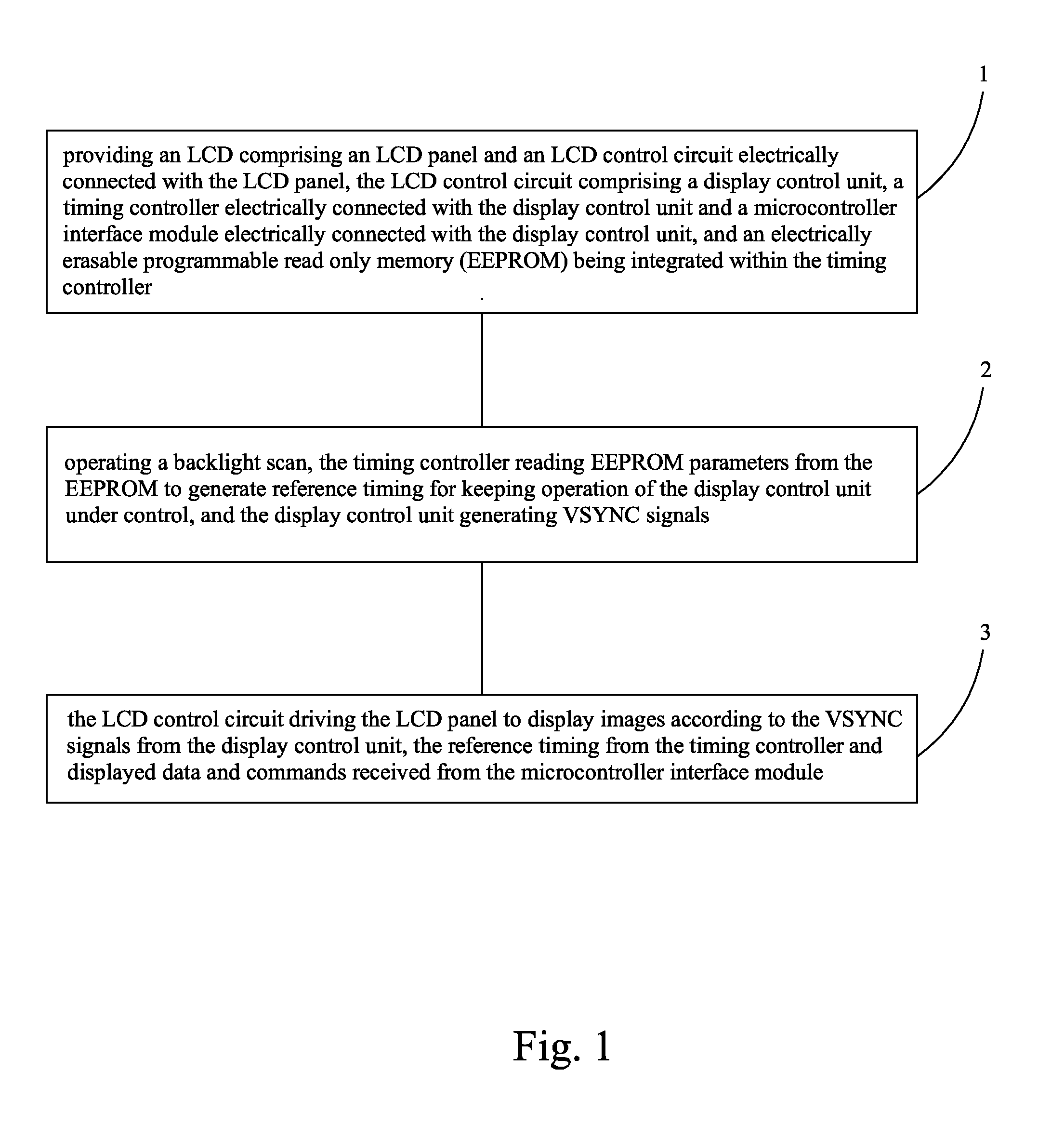
[0039]Please refer to FIG. 1 to FIG. 3, the present invention provides a method for driving an LCD comprising the following steps:

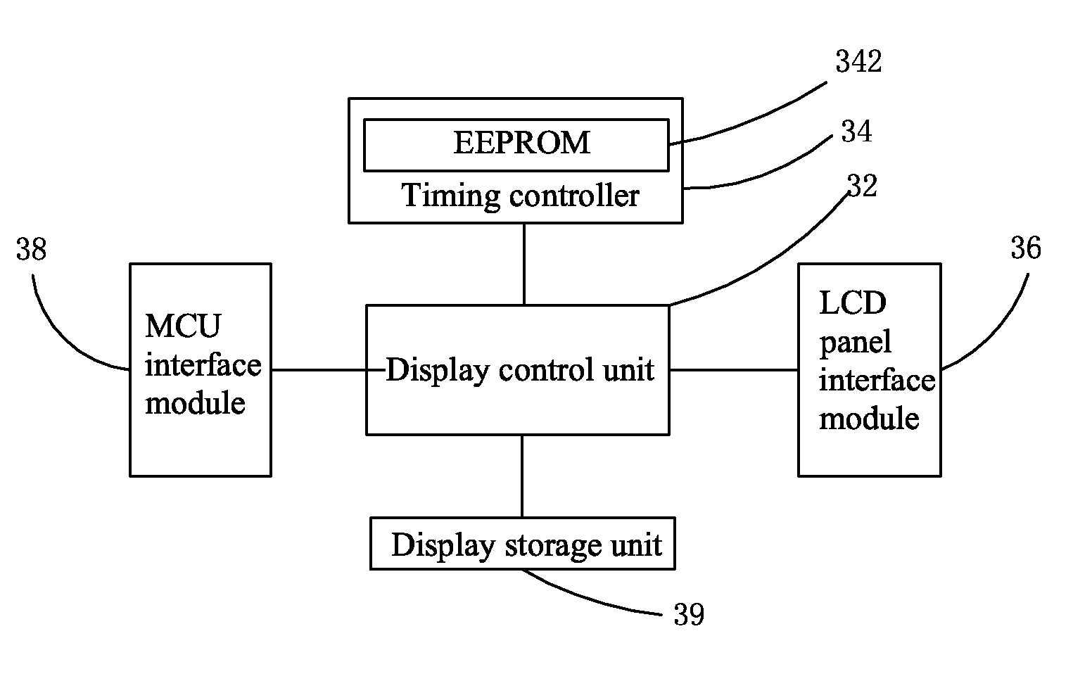
[0040]Step 1: Provide an LCD 20 comprising an LCD panel 24 and an LCD control circuit 22 electrically connected with the LCD panel 24. The LCD control circuit 22 comprises a display control unit 32, a timing controller 34 electrically connected with the display control unit 32 and a microcontroller (MCU) interface module 38 electrically connected with the display control unit 32. An EEPROM 342 is integrated within the timing controller 34.

[0041]A main board system end (not shown) electrically connected with the MCU interface module 38 is provided so that the main board system end transmits control signals to the display control unit 32 through the MCU interface module 38.

[0042]EEPROM parameters are pre-stored in t...


PUM


Abstract

The present invention provides a driving method for an LCD and an LCD control circuit using the method thereof. The method includes three steps. Step 1 is that providing an LCD comprising an LCD panel and an LCD control circuit, including a display control unit, a timing controller and a microcontroller interface module, and an electrically erasable programmable read only memory (EEPROM) is integrated into the timing controller. Step 2 is to operate a backlight scan, the timing controller reads EEPROM parameter from the installed EEPROM to generate reference timing for keeping operation of the display control unit under control, and the display control unit generates VSYNC signals. Step 3 is that the control circuit drives the panel to display images. The timing controller in the method integrating the EEPROM simplifies circuit design and raises product integration to reduce producing costs.

Description

BACKGROUND OF THE INVENTION[0001]1. Field of the Invention[0002]The present invention relates to an electronic field technology, more particularly, to a method for driving a liquid crystal display (LCD) and an LCD control circuit using the method.[0003]2. Description of the Prior Art[0004]Technology is developing fast nowadays. Manufacturers design various information products to meet different demands for public. Most of displays in the past are cathode ray tube (CRT) monitors. Such displays have faults such as bulk, heavy power consumption, and radiation to harm users' health. Therefore, LCDs have been used gradually on the market in place of traditional CRT displays.[0005]An LCD with various advantages like slimness, energy-saving, non-radiation, etc, has been applied broadly. Most of LCDs on the market are backlight type LCD comprising an LCD panel and a backlight module. The working principle of an LCD panel is that an alignment of liquid crystal molecules between two parallel ...

Claims


Application Information

Patent Timeline
Patent Type & Authority Applications(United States)
IPC IPC(8): G09G3/36G09G3/34
CPCG09G3/36G09G2310/08G09G2310/0291G09G3/3406G09G3/003G09G2370/042
Inventor WU, DONGGUANG
Owner SHENZHEN CHINA STAR OPTOELECTRONICS TECH CO LTD
Learn More