
Dynamically calibrating magnetic sensors

a magnetic sensor and dynamic calibration technology, applied in the field of dynamic calibration of magnetic sensors, can solve the problems of inaccurate heading measurements, inability to appropriately account for the shift in the magnetic field caused by the technique, and inability to accurately account for the shift in the magnetic field seen at the sensor

Active Publication Date: 2014-09-18
TAHOE RES LTD
View PDF5 Cites 5 Cited by
  • Summary
  • Abstract
  • Description
  • Claims
  • Application Information

AI Technical Summary

Benefits of technology

The present invention relates to a method for dynamically calibrating magnetic sensors in computing devices. The technical effect of the invention is to account for shifts in the magnetic field caused by changes in the system states of components of the computing device, such as the battery and power state of the components. Current techniques only account for shifts in the magnetic field caused by changes in the external environment, resulting in incorrect orientation output of the computing device. The invention uses a computing device's centroid of the magnetic sensor output as a reference for calibration, taking into account the magnetic field induced by the platform of the computing device. This allows for accurate calibration of the magnetic sensor even when the platform is in a different state.

Problems solved by technology

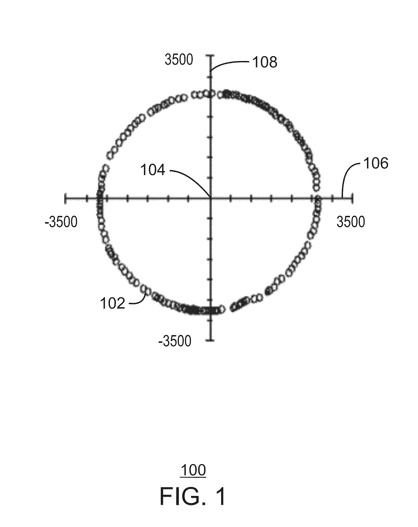
However, interference induced by the platforms of the computing devices may impede the proper functioning of the magnetic sensors, resulting in inaccurate heading measurements.
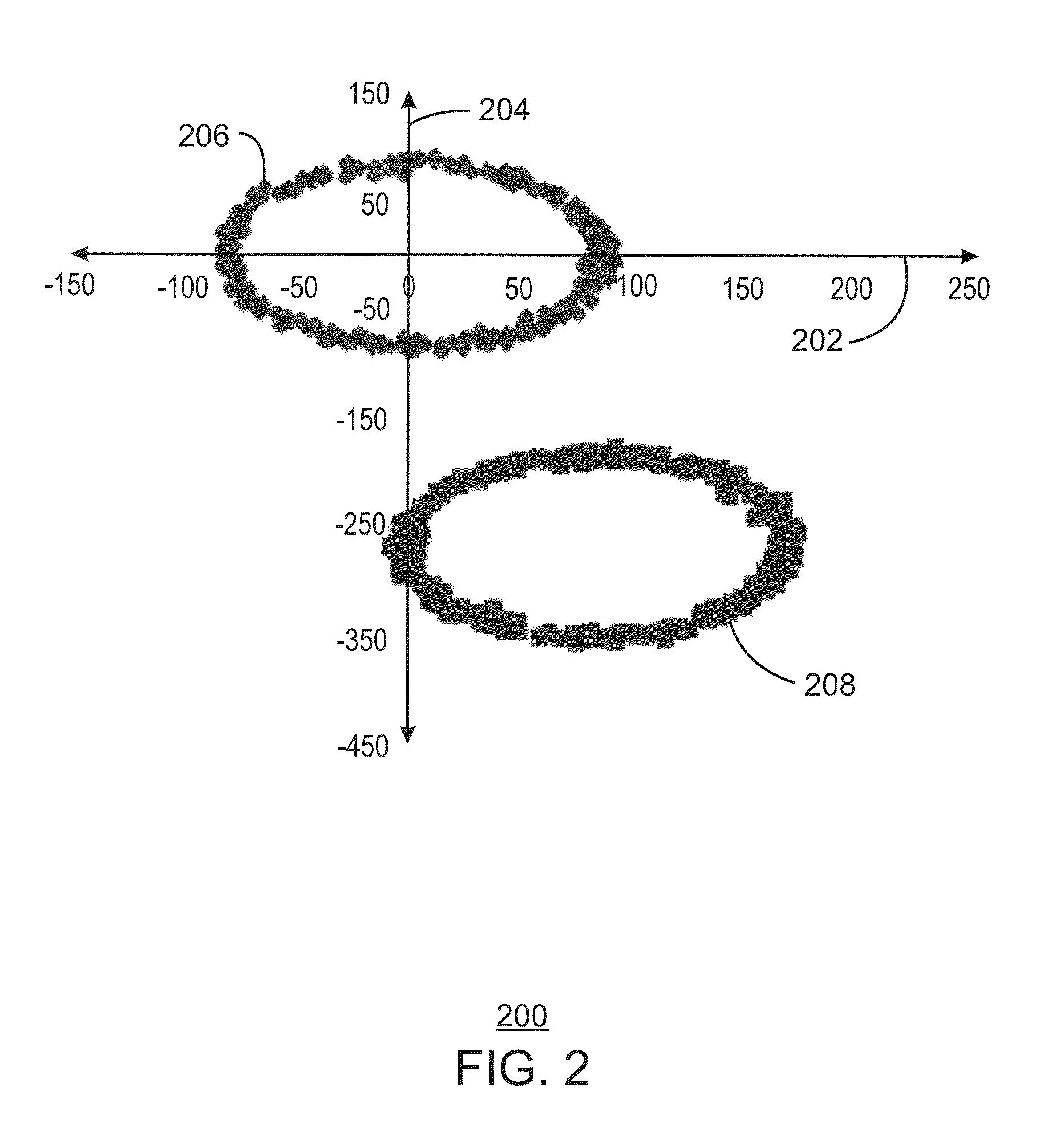
However, such techniques do not appropriately account for shifts in the magnetic field caused by changes in the system states of the components of the computing device.
For example, such techniques do not account for shifts in the magnetic field seen at the sensor that are caused by changes in the power state of the computing device that may occur when the battery of the computing device is being charged or the overall power consumption of the computing device changes.
As a result, the orientation output of the computing device reading the magnetic sensor will be incorrect during the time between the occurrence of the physical shift in the magnetic field and the detection and calculation of the shift in the magnetic field.

Method used


Image

  • Dynamically calibrating magnetic sensors
  • Dynamically calibrating magnetic sensors
  • Dynamically calibrating magnetic sensors

Examples


example 1

[0057]A computing device is provided herein. The computing device includes a sensor hub and a magnetic sensor communicably coupled to the sensor hub. The magnetic sensor is configured to collect sensor data corresponding to the computing device. The computing device also includes a processor and a storage device. The storage device includes processor executable code that, when executed by the processor, is configured to determine a system state of the computing device and send the determined system state of the computing device to the sensor hub. The sensor hub is configured to dynamically calibrate the magnetic sensor based on the sensor data collected via the magnetic sensor and the determined system state of the computing device.

[0058]The sensor hub may be configured to dynamically calibrate the magnetic sensor by determining a calibration offset value for a system state change event corresponding to the determined system state of the computing device, and using the calibration o...

example 2

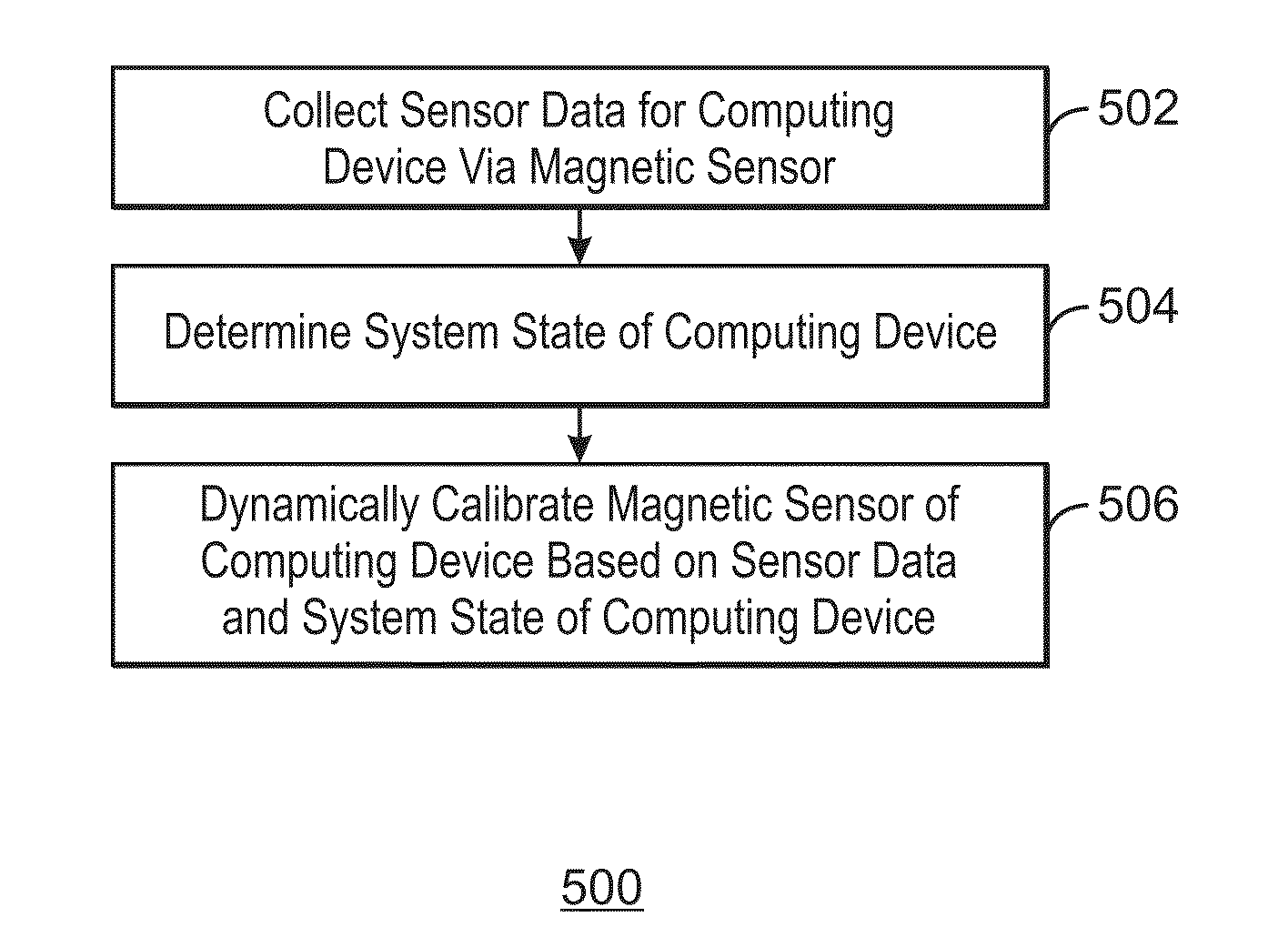
[0061]A method for dynamically calibrating a magnetic sensor of a computing device is provided herein. The method includes collecting sensor data for a computing device via a magnetic sensor, determining a system state of the computing device, and dynamically calibrating the magnetic sensor of the computing device based on the sensor data and the system state of the computing device.

[0062]Dynamically calibrating the magnetic sensor may include determining a calibration offset value for a system state change event corresponding to the determined system state of the computing device. The calibration offset value may be used to correct an output of the magnetic sensor including the sensor data. The corrected output of the magnetic sensor may be provided to an application executing on the computing device.

[0063]Furthermore, dynamically calibrating the magnetic sensor may include determining a calibration offset value for each of a number of system state change events corresponding to th...

example 3

[0064]At least one machine readable medium is provided herein. The machine readable medium includes instructions stored therein that, in response to being executed on a processor, cause the processor to determine an output of a magnetic sensor residing within a computing device. The output includes sensor data. The instructions cause the processor to determine a system state of the computing device and determine a calibration offset value for each of a number of system state change events corresponding to the determined system state of the computing device. The instructions also cause the processor to calculate a combined calibration offset value by summing the calibration offset values for the system state change events and calculate a corrected output of the magnetic sensor by subtracting the combined calibration offset value from a value of the output of the magnetic sensor. The instructions further cause the processor to dynamically calibrate the magnetic sensor by updating the ...


PUM


Abstract

A computing device, system, apparatus, and at least one machine readable medium for dynamically calibrating a magnetic sensor are described herein. The computing device includes a sensor hub and a magnetic sensor communicably coupled to the sensor hub. The magnetic sensor is configured to collect sensor data corresponding to the computing device. The computing device also includes a processor that is configured to execute stored instructions and a storage device that stores instructions. The storage device includes processor executable code that, when executed by the processor, is configured to determine a system state of the computing device and send the determined system state of the computing device to the sensor hub. The sensor hub is configured to dynamically calibrate the magnetic sensor based on the sensor data collected via the magnetic sensor and the determined system state of the computing device.

Description

TECHNICAL FIELD[0001]The present invention relates generally to dynamic calibration of magnetic sensors. More specifically, the present invention relates to a computing device, method, apparatus, and at least one machine readable medium for dynamically calibrating a magnetic sensor based on the system state of the computing device in which the magnetic sensor resides.BACKGROUND ART[0002]Magnetic sensors are often integrated within the platforms of computing devices and are used as compasses to measure or detect heading information, e.g., information relating to the direction the computing device is pointing. Such heading information may be used for navigation applications, perceptual computing applications, gaming applications, or the like. However, interference induced by the platforms of the computing devices may impede the proper functioning of the magnetic sensors, resulting in inaccurate heading measurements. Specifically, the magnetic field induced by the platform of a computi...

Claims


Application Information

Patent Timeline
IPC IPC(8): G01R35/00
CPCG01R35/005G01C17/28G01C17/38G01R33/0035G01R33/0206G01R33/025G01R35/00
Inventor BRIST, GARY A.DANIEL, KEVIN J.COWAN, MELISSA A.
Owner TAHOE RES LTD
Learn More