
Mecanum wheel and mecanum-wheeled vehicle

a technology of mecanum wheels and wheels, which is applied in the direction of multiple wheel assemblies, hubs, and spoked wheels, can solve the problems of failure to achieve a breakthrough or widely distribute the mecanum wheel drive, and the failure of the technology breakthrough

Active Publication Date: 2014-08-21
OMNIROLL
View PDF2 Cites 26 Cited by
  • Summary
  • Abstract
  • Description
  • Claims
  • Application Information

AI Technical Summary

Benefits of technology

The invention is about a vehicle design that uses Mecanum wheels. These wheels have rollers that are inclined to the rim axis, which allows the wheels to handle uneven surfaces. The rims are not rigidly connected to each other, but they can move relative to each other to compensate for any irregularities in the surface. The vehicle is also connected to a damping element to absorb the forces when the wheels hit the surface. The rollers on the wheels are held on a common carrier, and the damping element engages with the rollers at arm ends. This allows for flexibility in the movement of the wheels. The wheel is mounted through a bearing arm, which is dampened by a torsion spring. The use of rubber spring elements with a slightly progressive spring characteristic curve helps to improve the performance of the vehicle. The technical effects of this design include improved stability, reduced vibration, and better handling of uneven surfaces.

Problems solved by technology

In the past, attempts to achieve a breakthrough or widely distribute the Mecanum wheel drive were made in vain.
The breakthrough of the technology has not been successful so far, presumably since during the rolling of the Mecanum wheels during the change in contact between two rollers which are adjacent in circumferential direction to the surface undefined driving states briefly result, in which the vehicle “floats” or does not follow a desired movement path in a defined manner.

Method used


Image

  • Mecanum wheel and mecanum-wheeled vehicle
  • Mecanum wheel and mecanum-wheeled vehicle
  • Mecanum wheel and mecanum-wheeled vehicle

Examples


Embodiment Construction

[0030]In the figures, same elements and elements with the same function are marked with the same reference characters.

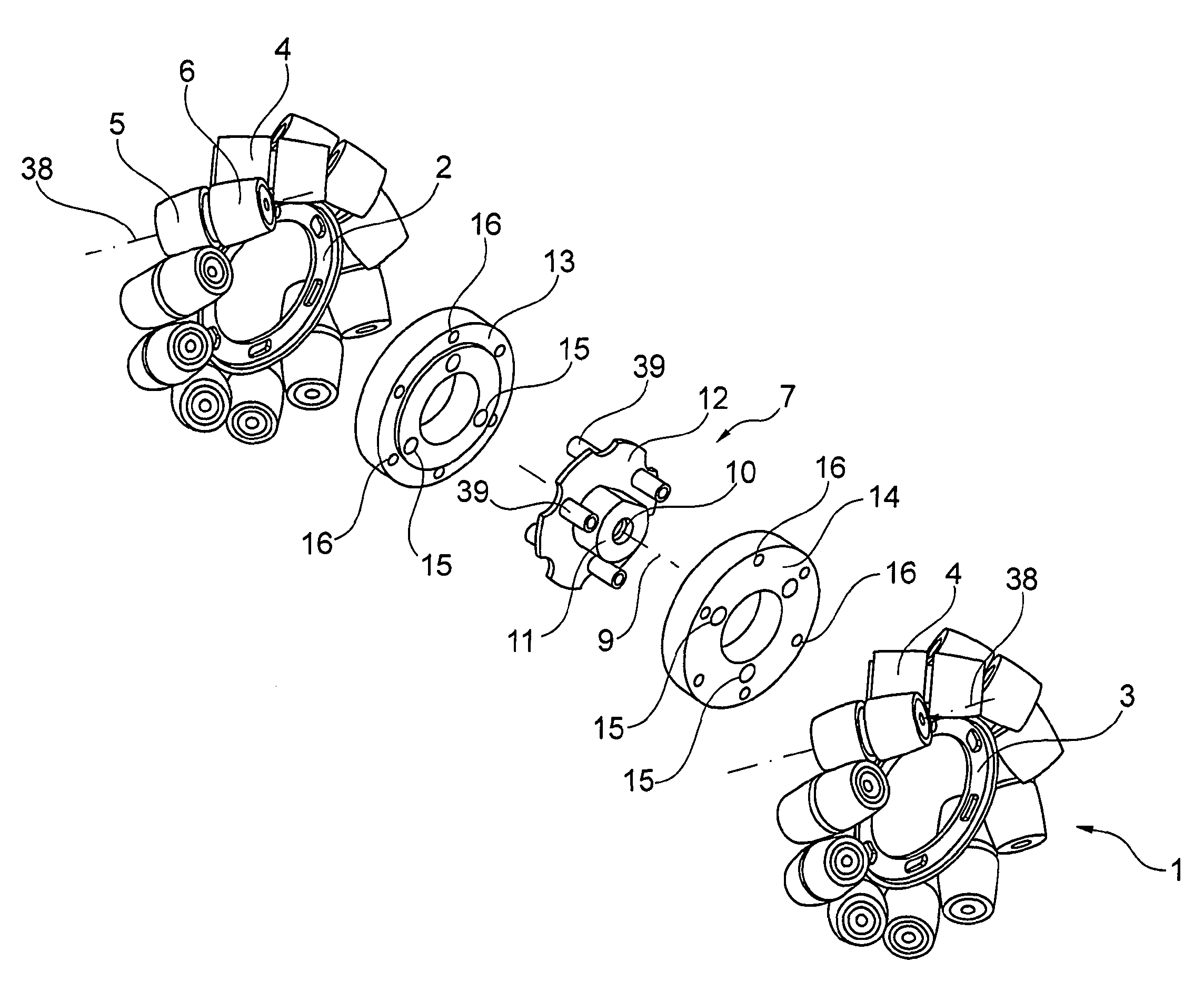
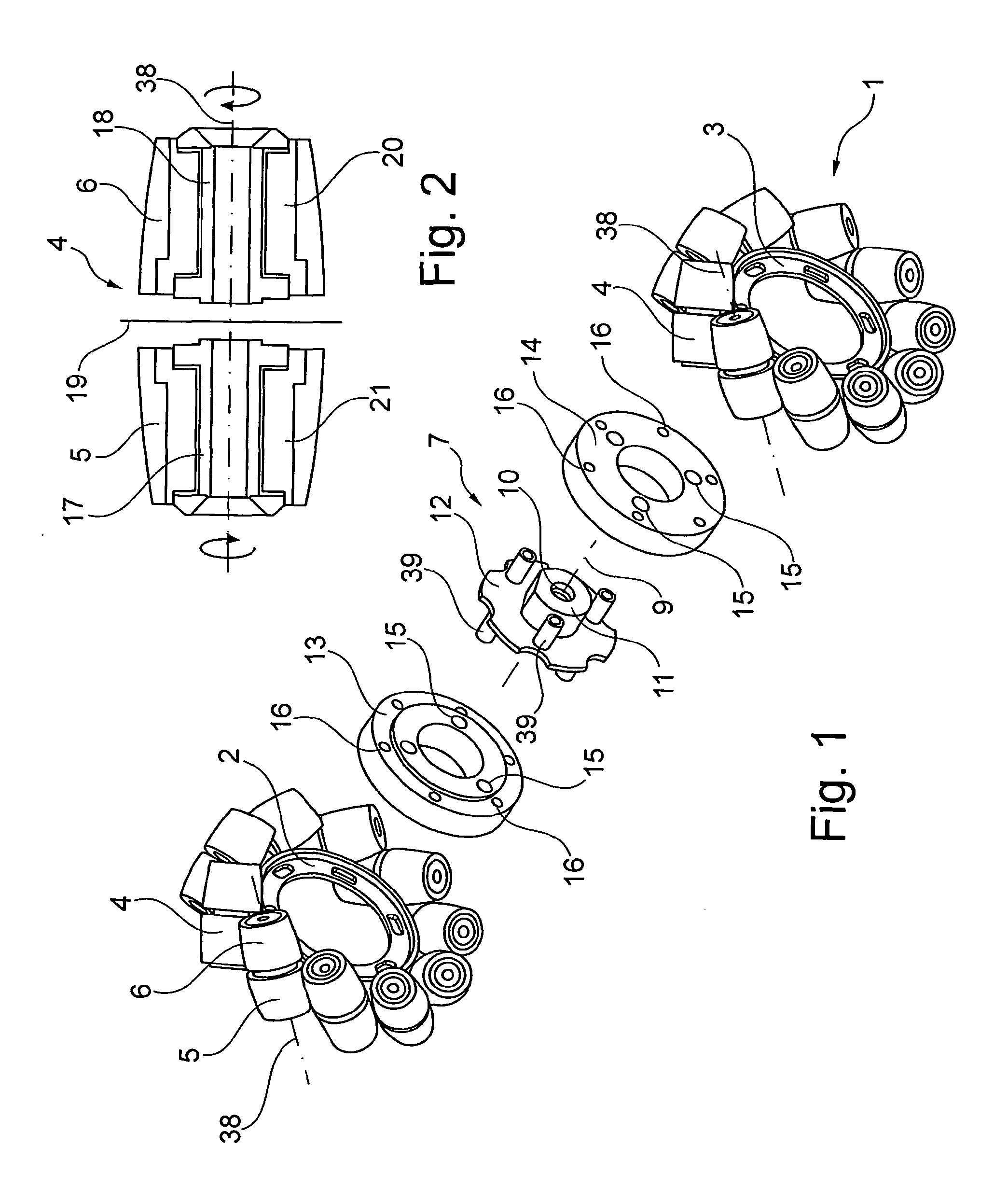
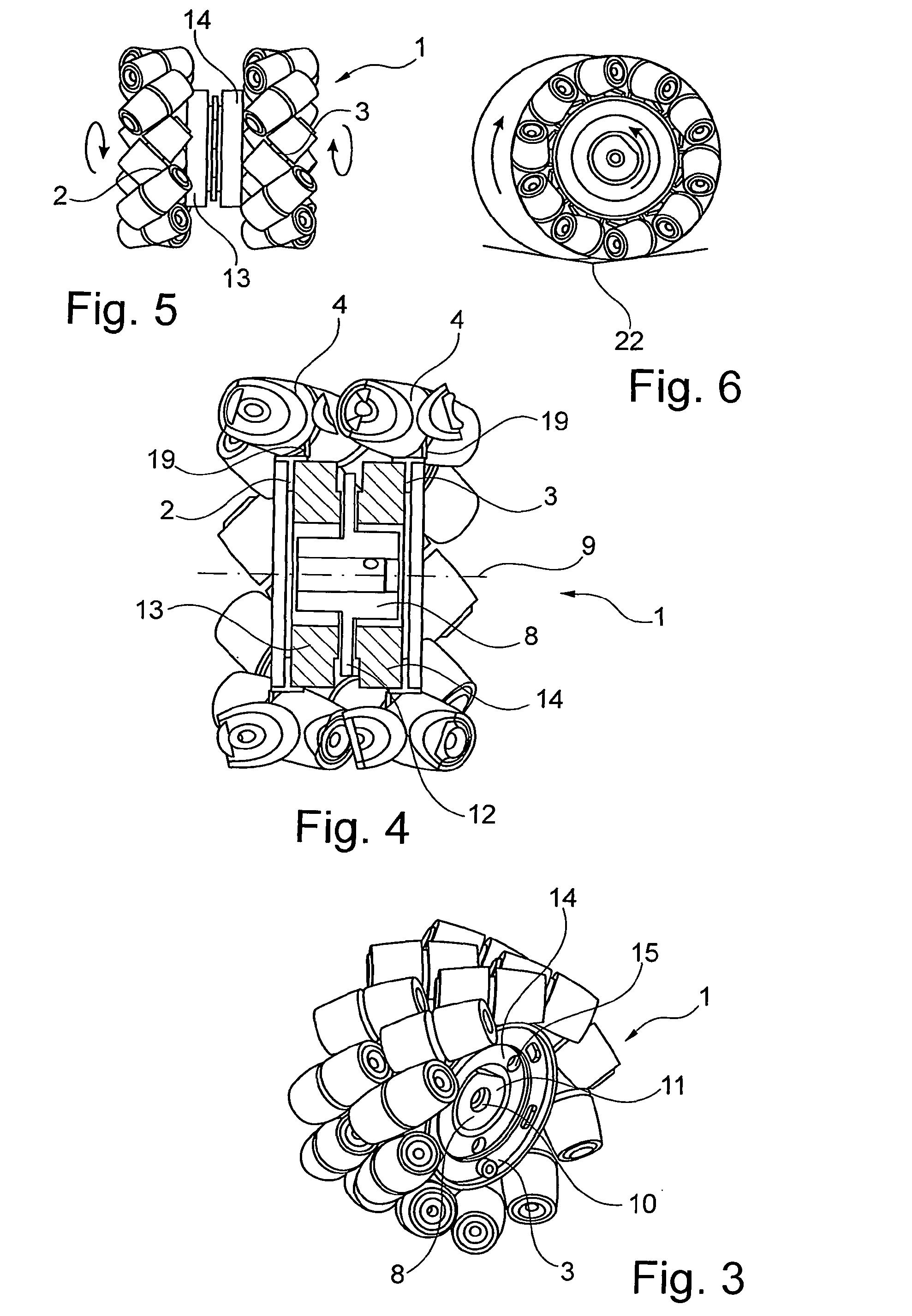
[0031]With the help of FIG. 1, a preferred construction of a Mecanum wheel 1 according to the invention is described. This comprises in the shown exemplary embodiment 2 rims each formed as wheel rim, namely a first rim 2 and a second rim 3. Both rims 2, 3 are jointly (coupled) driveable with a drive that is not shown.

[0032]It is evident that on each rim 2, 3 multiple rollers 4 arranged next to one another in circumferential direction are rotatably arranged, wherein the rollers 4 have a barrel-shaped sleeve contour, the diameter of which decreases with increasing spacing from the roller middle. Each roller 4 consists of two part rollers, namely a first and a second part roller 5, 6, which will still be explained later on in particular by means of FIG. 5. The rollers 4 of both rims 2, 3 are rotatable about an imaginary roller axis 38 each, which extends angularly to th...


PUM


Abstract

A Mecanum wheel having a first wheel rim (2) which bears a multiplicity of rollers (4) which are arranged adjacent to one another in a circumferential direction and which are in each case mounted so as to be rotatable about a roller axis of rotation (38) arranged at an angle with respect to a first wheel rim axis of rotation (24), wherein said Mecanum wheel is characterized by a second wheel rim (3) which can be driven together with the first wheel rim (2) by means of a common drive shaft (33) and which bears a multiplicity of rollers (4) which are arranged adjacent to one another in a circumferential direction and which are in each case mounted so as to be rotatable about a roller axis of rotation (38) arranged at an angle with respect to a second wheel rim axis of rotation (25), which second wheel rim is connected to the first wheel rim (2) via damping means (7) formed so as to permit a limited relative movement of the first and the second rim (3) relative to one another. It is provided according to the invention that the damping means (7) are formed so as to permit a damped, limited relative movement between the first and the second wheel rim (2, 3) in the circumferential direction and / or perpendicular to a Mecanum wheel axis of rotation (9) and / or perpendicular to the first and / or to the second wheel rim axis of rotation (25) and / or at a tilt angle relative to one another.

Description

BACKGROUND OF THE INVENTION[0001]The invention relates to a Mecanum wheel for omnidirectional driving manoeuvres without mechanical steering, having a first rim carrying rollers arranged in a circumferential direction next to one another which are rotatably mounted about a roller axis of rotation that is arranged at an angle to a first rim axis of rotation. In other words, the rollers are rotatable about roller axes of rotation which are arranged at an angle to the first rim axis of rotation. Furthermore, the invention relates to a vehicle having a plurality of such Mecanum wheels.[0002]Mecanum wheels are generally known. On the circumference of the rim of the wheel, multiple rotatably mounted rollers which as a rule are barrel-shaped are rotatably attached mostly at an angle of 45° to the axis of the rim and thus of the wheel. It is not the rim but exclusively the aforementioned rollers that establish contact with the ground. The rollers have no direct drive and can freely rotate a...

Claims


Application Information

Patent Timeline
Patent Type & Authority Applications(United States)
IPC IPC(8): B60B19/00
CPCB60B19/003B60B11/02B60B19/125B60B33/0028B60B33/0042B60B33/0044B60B33/0052B60B33/045B60B2900/131B60Y2200/10
Inventor ZDRAHAL, PAVELUEBELHART, BAUDOUINSPINDLER, ZDENEK
Owner OMNIROLL
Learn More