
Arc runners suitable for DC molded case circuit breakers and related methods

a technology of arc runners and circuit breakers, applied in the field of arc runners, can solve the problems of long arcing time, and high temperature, and achieve the effect of reducing arcing time and inhibiting damage to the arc chute and/or breaker

Active Publication Date: 2014-07-24
EATON INTELLIGENT POWER LTD
View PDF6 Cites 3 Cited by
  • Summary
  • Abstract
  • Description
  • Claims
  • Application Information

AI Technical Summary

Benefits of technology

The present invention aims to provide arc runners that can speed up the process of getting energy released from an electric arc and prevent damage to the equipment used for this process.

Problems solved by technology

Since the arc runner provides a pathway for the arc to follow to the arc chute, it is subject to intensely high temperatures.
The lack of engagement between the arc and the lower arc plates may cause longer arcing time and damage to the arc chute and breaker.

Method used


Image

  • Arc runners suitable for DC molded case circuit breakers and related methods
  • Arc runners suitable for DC molded case circuit breakers and related methods
  • Arc runners suitable for DC molded case circuit breakers and related methods

Examples


Embodiment Construction

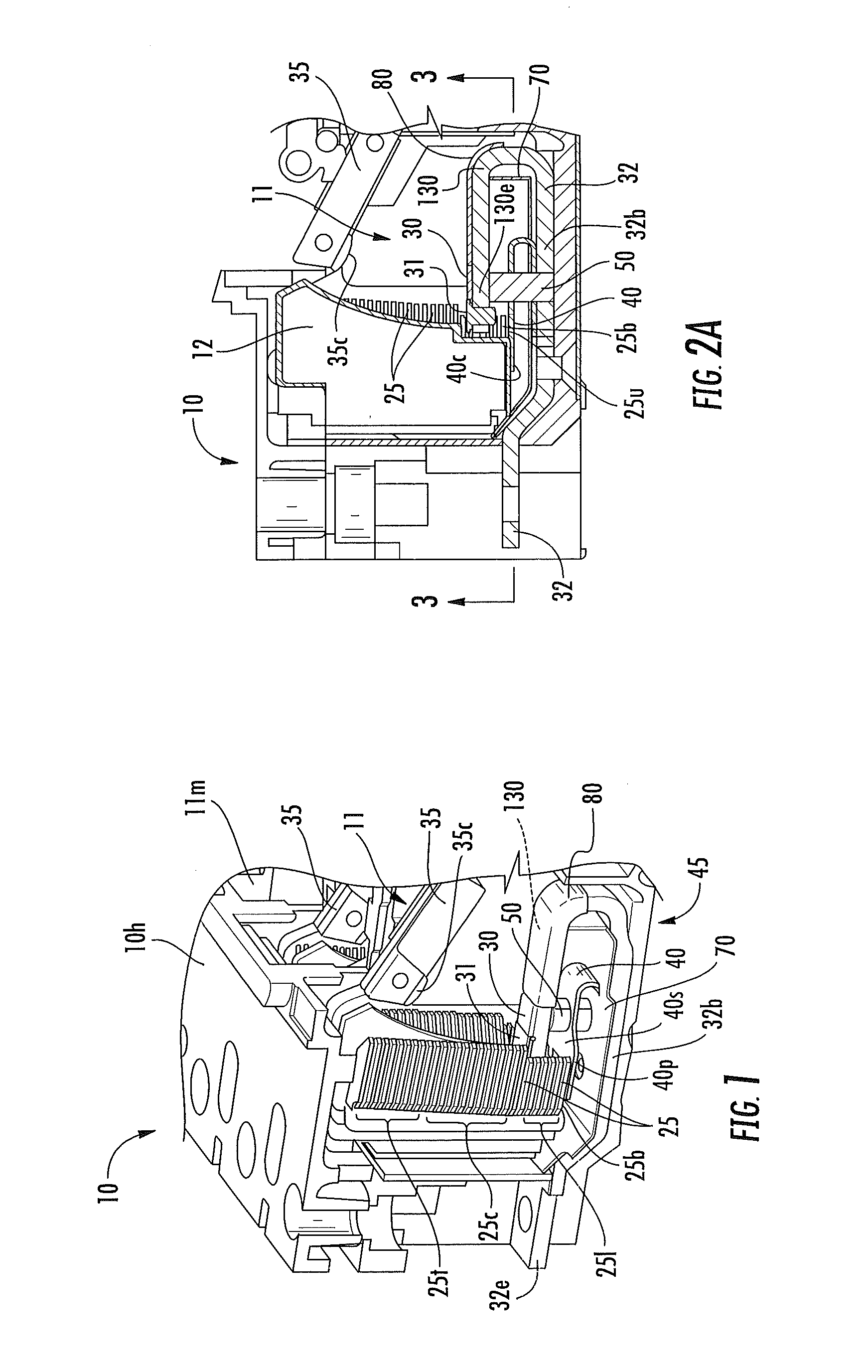
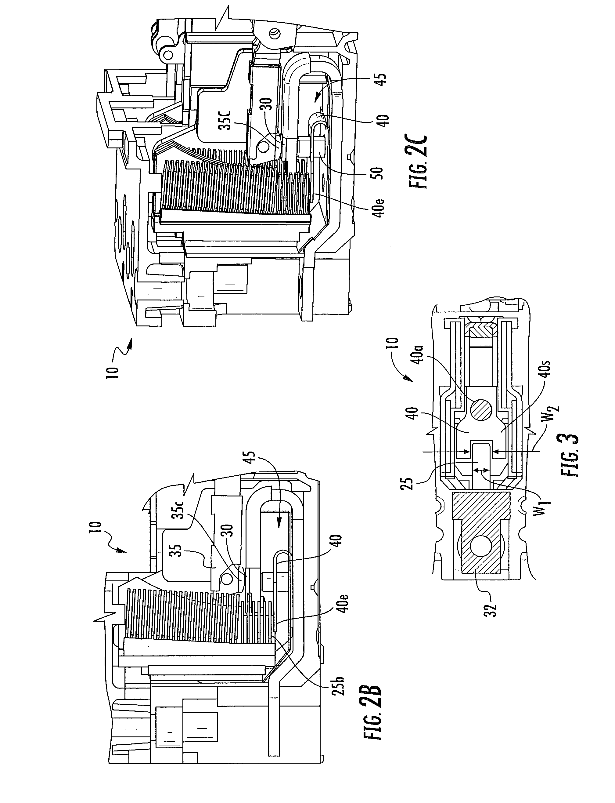
[0006]Embodiments of the present invention are directed to arc runners that can reduce arcing time and / or inhibit damage to the arc chute and / or breaker.

[0007]Some embodiments are directed to bi-directional direct current (DC) circuit breakers.

[0008]Some embodiments are directed to circuit breakers that include: (a) an arc chamber; (b) an arc chute comprising a plurality of arc plates in the arc chamber; (c) a line conductor in the arc chamber, the line conductor having a lower body portion and an upwardly extending arm with a free end, the arm residing above the lower body portion; (d) a stationary contact held by the arm of the line conductor, the stationary contact residing adjacent to the arc plates; and (e) a non-ferromagnetic arc runner held by the line conductor in the arc chamber. The arc runner is at least one of (i) attached to the lower body portion of the line conductor and resides forward of the stationary contact with a portion residing under a bottom arc plate or (ii)...


PUM


Abstract

Circuit breakers include an arc chamber and an arc chute comprising a plurality of arc plates in the arc chamber. The circuit breakers also include a line conductor assembly with at least one arc runner attached to a line conductor in the arc chamber. The arc runner can extend below but adjacent to a bottom arc plate to thereby guide a respective arc into the arc chute.

Description

FIELD OF THE INVENTION[0001]The present invention relates to arc runners used with circuit breakers.BACKGROUND OF THE INVENTION[0002]Circuit breakers are one of a variety of overcurrent protection devices used for circuit protection and isolation. The circuit breaker provides electrical protection whenever an electric abnormality occurs. In a circuit breaker, current enters the system from a power line and passes through a line conductor to a stationary contact fixed on the line conductor, then to a movable contact. The movable contact can be fixedly attached to an arm and the arm can be mounted to a rotor. As long as the stationary and movable contacts are in physical contact, current passes from the stationary contact to the movable contact and out of the circuit breaker to down line electrical devices.[0003]In the event of an overcurrent condition (e.g., a short circuit), extremely high electromagnetic forces can be generated. The electromagnetic forces repel the movable contact ...

Claims


Application Information

Patent Timeline
Patent Type & Authority Applications(United States)
IPC IPC(8): H01H33/20
CPCH01H9/345H01H33/20H01H73/18H01H9/46
Inventor PUHALLA, CRAIG JOSEPHZHOU, XINSISLEY, JAMES PATRICKGULA, LANCEJANUSEK, MARK A.
Owner EATON INTELLIGENT POWER LTD
Learn More