
Valve manifold box

a manifold box and valve technology, applied in the field of valve manifold boxes, can solve the problems of saving maintenance costs and achieve the effect of saving maintenance costs and easy collection and draining

Inactive Publication Date: 2014-07-24
TAIWAN PURITIC +1
View PDF8 Cites 22 Cited by
  • Summary
  • Abstract
  • Description
  • Claims
  • Application Information

AI Technical Summary

Benefits of technology

The present invention is a valve manifold box for conveying chemicals that is made using injection molding. This design prevents chemicals from leaking outside and allows for easy collection and draining of liquid. Additionally, the changes in inclination angle of the inside surface at the bottom sidewall help improve the flow of liquid through the valve manifold box. The design also reduces the need for maintenance, saving money.

Problems solved by technology

Moreover, since it is unnecessary to frequently maintain the valve manifold box, maintenance costs are saved.

Method used


Image

  • Valve manifold box
  • Valve manifold box
  • Valve manifold box

Examples


Embodiment Construction

[0016]The detailed explanation of the present invention is described as follows. The described preferred embodiments are presented for purposes of illustrations and description, and they are not intended to limit the scope of the present invention.

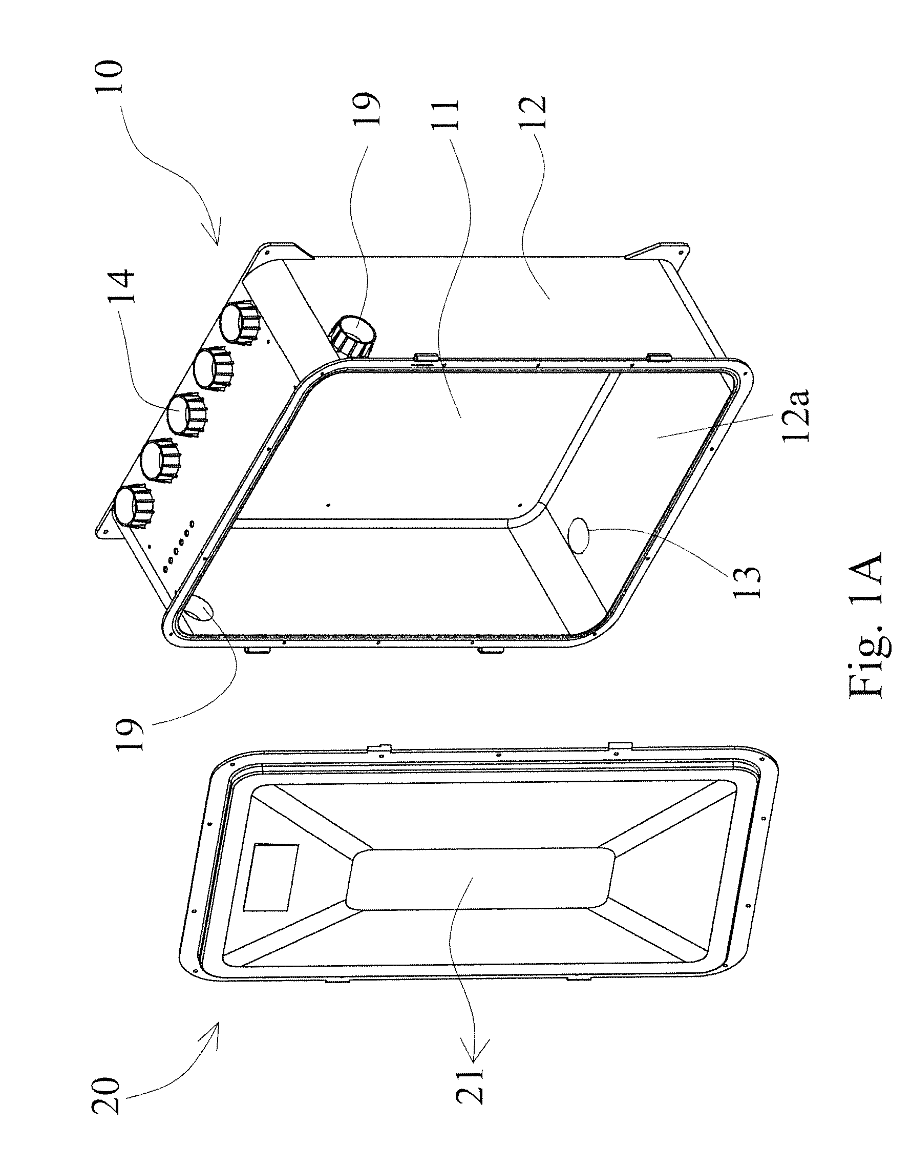
[0017]First referring to FIGS. 1A and 1B, in one embodiment of the present invention, the valve manifold box comprises a chamber 10 and a front cover 20. The chamber 10 is manufactured by injection molding and is one-piece construction. The chamber 10 comprises a back board 11, a sidewall 12, at least an outfall 13, and multiple fittings 14. The sidewall 12 erects from the back board 11 to form a space therein and a front opening opposite to the back board 11. The space is used for accommodating multiple pneumatic valves V and multiple pipelines P inside the chamber (as shown in FIG. 1B), and an inside surface at the bottom sidewall 12a has changes in an inclination angle θ for collecting the liquid within the chamber 10. The outfall 13 is...


PUM


Abstract

A valve manifold box comprises a chamber and a front cover. Significantly, the chamber is manufactured by injection molding and is one-piece construction. Moreover, the chamber comprises a back board, a sidewall, at least an outfall, and multiple fittings and inside surface at the bottom sidewall has changes in an inclination angle for collecting the liquid within the chamber. By means of injection molding, one piece construction of the chamber is obtained such that it prevents chemicals from leaking outside. Besides, by using the design that the inside surface at the bottom sidewall has changes in an inclination angle, liquid can be easily collected and drained. Also, since it is unnecessary to frequently maintain the valve manifold box, maintenance costs are saved.

Description

BACKGROUND OF THE INVENTION[0001]1. Field of the Invention[0002]The present invention relates to a valve manifold box, and more particularly to a valve manifold box for conveying chemicals.[0003]2. Description of the Prior Art[0004]For semiconductor industry or electronic industry, chemicals such as acids or alkalis are usually used for etching, cleaning, surface modification, etc. Thus, chemical supply systems must be established in factories to supply different species of chemicals in desired flow rate through pipelines to equipments during manufacturing processes. Generally, chemical supply systems comprise valve manifold boxes in the factory to convey chemicals. However, after long term use of pipelines in valve manifold boxes, chemicals leakage happens. Because valve manifold boxes are assembled by welding or screwing multiple pieces of sheets together, it may cause seams or gaps at the junction between the plates. A common situation is that chemicals leakage from the pipelines...

Claims


Application Information

Patent Timeline
IPC IPC(8): F16K27/12
CPCF16K27/12Y10T137/7043
Inventor CHOU, CHIH-HSIENYEH, CHUNG-HSIUCHAN, ANTHONY KAI TAI
Owner TAIWAN PURITIC
Learn More