
Illuminated shoe

Inactive Publication Date: 2014-06-12
KIM JILL
View PDF8 Cites 15 Cited by
  • Summary
  • Abstract
  • Description
  • Claims
  • Application Information

AI Technical Summary

Benefits of technology

The patent describes a shoe that has several areas with lights. One area is around the sole of the shoe, with another area above the sole on the mid-portion of the shoe. These lights make the shoe easier to see in the dark.

Problems solved by technology

One particularly fastidious type of functional purchaser are the joggers, athletically-inclined people, and those whose jobs require heavy-duty lifting and other strenuous activities.

Method used


Image

  • Illuminated shoe
  • Illuminated shoe
  • Illuminated shoe

Examples


Embodiment Construction

[0022]According to an embodiment of the present invention, a unique Illuminated Shoe is used to provide a series of illuminated lights around a shoe for the purpose of fashion, or safety precautions for joggers or pedestrians. The present system is described in enabling detail below.

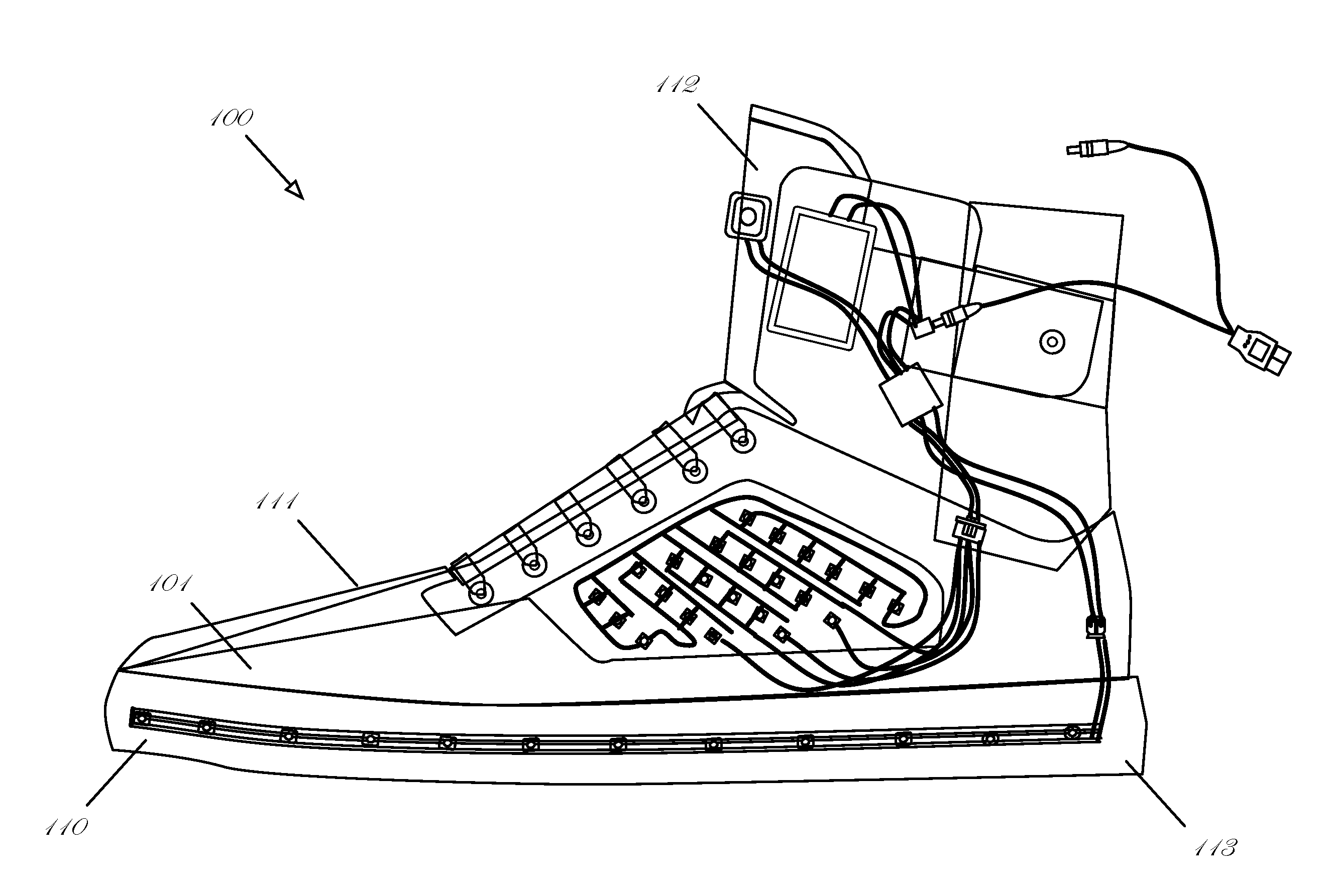
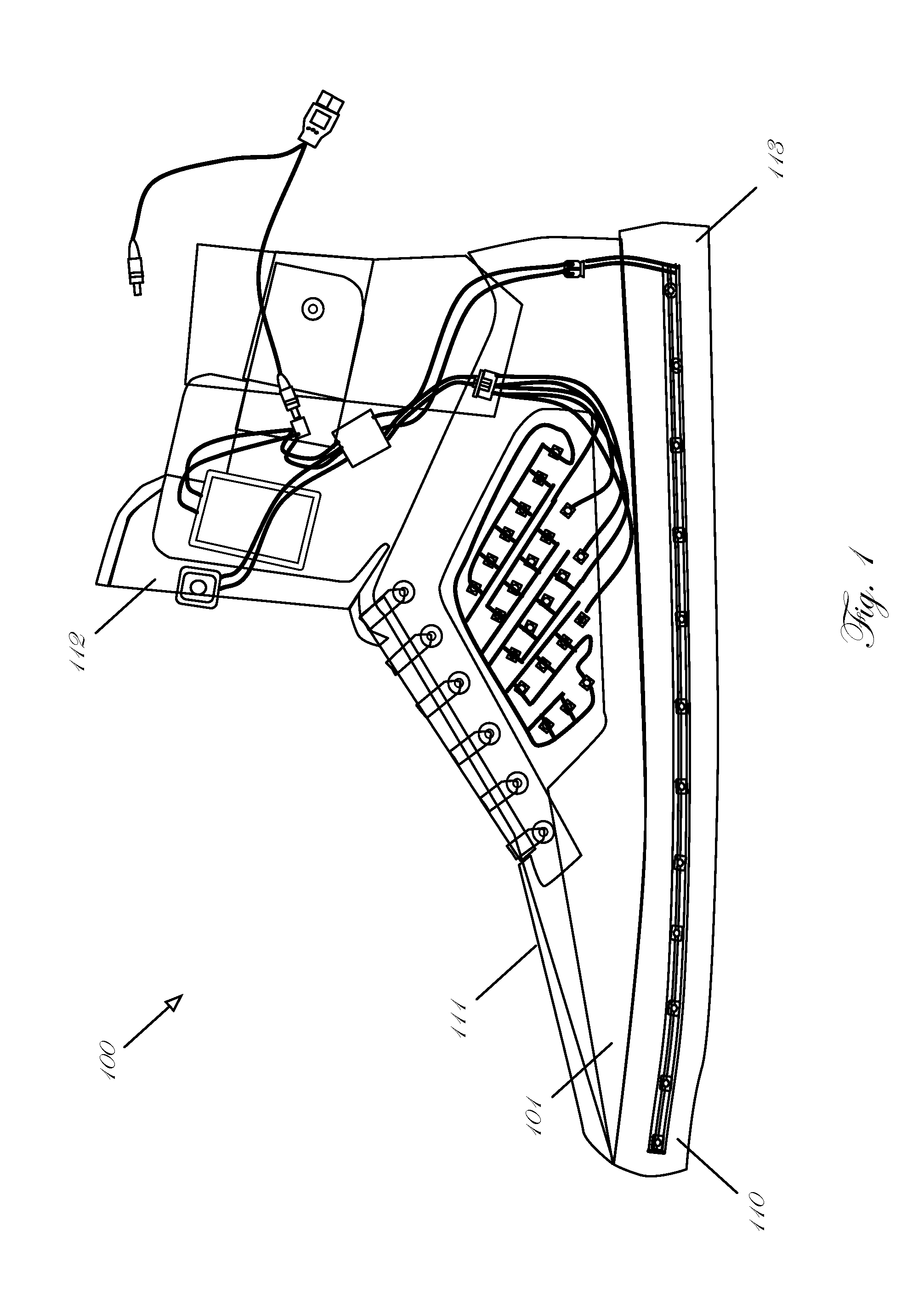
[0023]FIG. 1 is an illustration of an Illuminated Shoe 100 in accordance with one embodiment. In one embodiment, the Illuminated Shoe 100 includes Shoe 101, and Illumination Apparatus System 102. The system is illustrated in FIG. 4

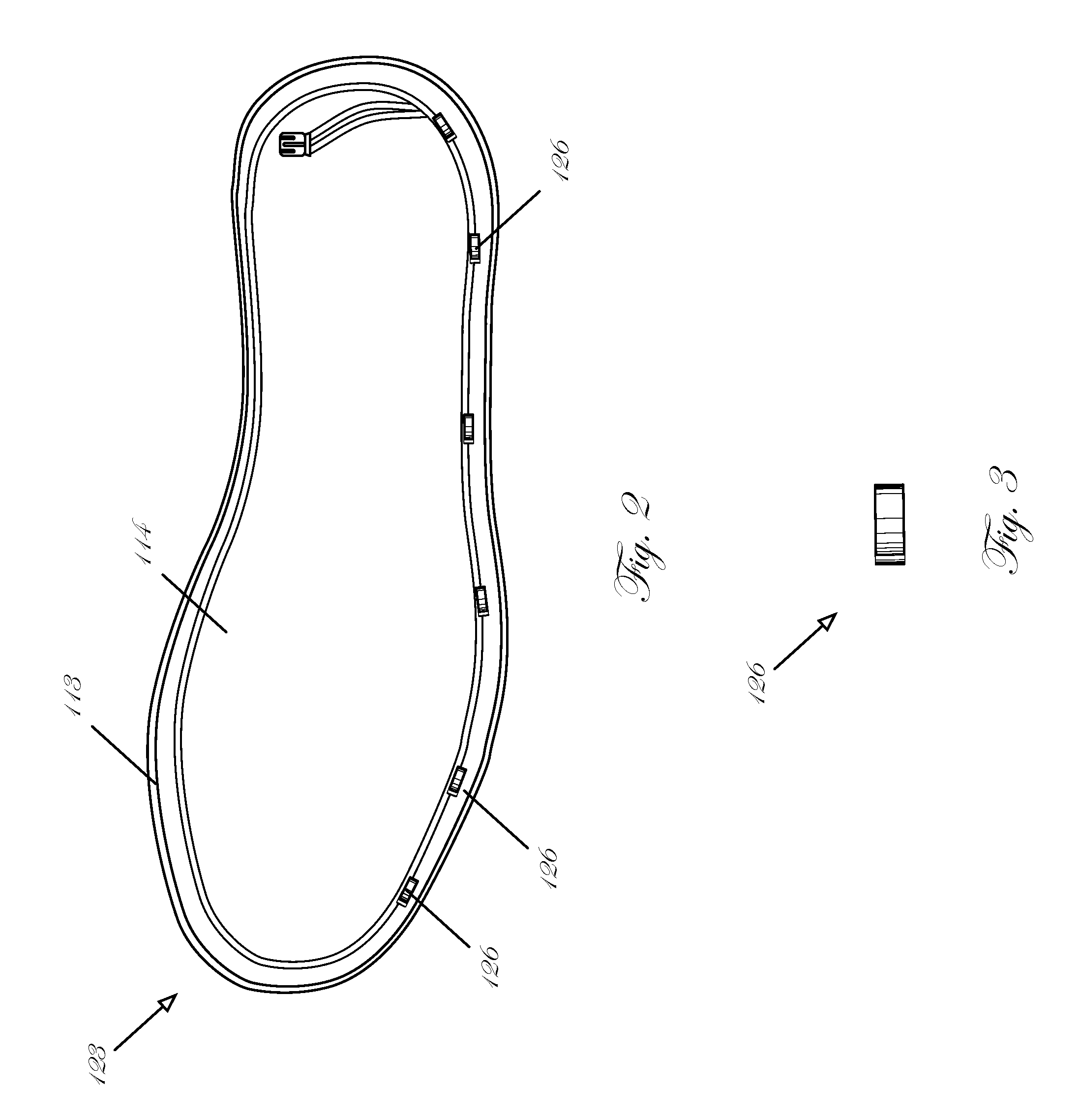
[0024]The shoe comprises a base 110, a first covering 111 and an upper covering 112. FIG. 2 illustrates that the base comprises a peripheral housing member 113 and a sole 114. Also illustrated in FIG. 2 is the PCB film 565 upon which a plurality of individual LED lights are affixed and through which a battery is in communication. FIG. 6 illustrates that PCB 575 can also be used to assemble the LED lights for positioning on the sides of the shoes in a similar fashion as the sole...


PUM


Abstract

In one embodiment, the Illuminated Shoe incorporates an Illumination Apparatus System. The base comprises a peripheral housing member and a sole. The PCB film upon which a plurality of individual LED lights are affixed and through which a battery is in communication. The PCB can also be used to assemble the LED lights for positioning on the sides of the shoes in a similar fashion as the soles. The peripheral housing member encases the sole. It should be noted that the illuminated shoe can be fabricated in a panoply of different styles such as high-top basketball shoes, or low-rise tennis shoes.

Description

FIELD OF THE INVENTION[0001]The present invention is in the area of shoes, and more specifically pertains to a shoe capable of emitting light from a plurality of regions.BACKGROUND OF THE INVENTION[0002]Most people purchase shoes based upon two overarching criteria: fashion and function. For purchasers that place more emphasis on function, factors that can figure largely into their selection include safety, comfort, and how the personal morphologies of their feet match the shoe. And for the fashion-forward purchasers, style is the paramount characteristic.[0003]One particularly fastidious type of functional purchaser are the joggers, athletically-inclined people, and those whose jobs require heavy-duty lifting and other strenuous activities. Among their chief concerns is alerting drivers at night their presence to avoid collisions. For this reason, many shoes are outfitted with reflective surfaces with the goal of safety in mind.[0004]For the more fashion-forward types, shoes which ...

Claims


Application Information

Patent Timeline
Patent Type & Authority Applications(United States)
IPC IPC(8): A43B23/24
CPCA43B23/24A43B3/36
Inventor KIM, JILL
Owner KIM JILL
Learn More