Optical assembly and laser alignment apparatus

a laser alignment and optical assembly technology, applied in the field of optical assembly or assembly, can solve the problems of noticeable shift in the position of the laser beam impinging on the photosensitive target, the tilting movement of the mounting mechanism relative, etc., and achieve the effect of accurately determining positions and alignments relativ

Inactive Publication Date: 2014-04-24
HAMAR LASER INSTR
View PDF11 Cites 2 Cited by
  • Summary
  • Abstract
  • Description
  • Claims
  • Application Information

AI Technical Summary

Benefits of technology

The patent describes an optical assembly that can be used in a laser alignment system. The assembly ensures that photosensitive targets can accurately determine positions and alignments relative to three mutually perpendicular axes and / or three mutually perpendicular planes even if the assembly tilts relative to the input beam due to changes in temperature or vibration. The technical effect of this invention is improved accuracy in laser alignment even in adverse conditions.

Problems solved by technology

The mounting mechanisms are subject to tilting movement relative to the input beam due to temperature related differential expansion and / or vibration.
Machines or vehicles operating near a laser alignment can cause a noticeable shift in the position of the laser beam impinging upon the photosensitive target.

Method used


Image

  • Optical assembly and laser alignment apparatus
  • Optical assembly and laser alignment apparatus
  • Optical assembly and laser alignment apparatus

Examples


Embodiment Construction

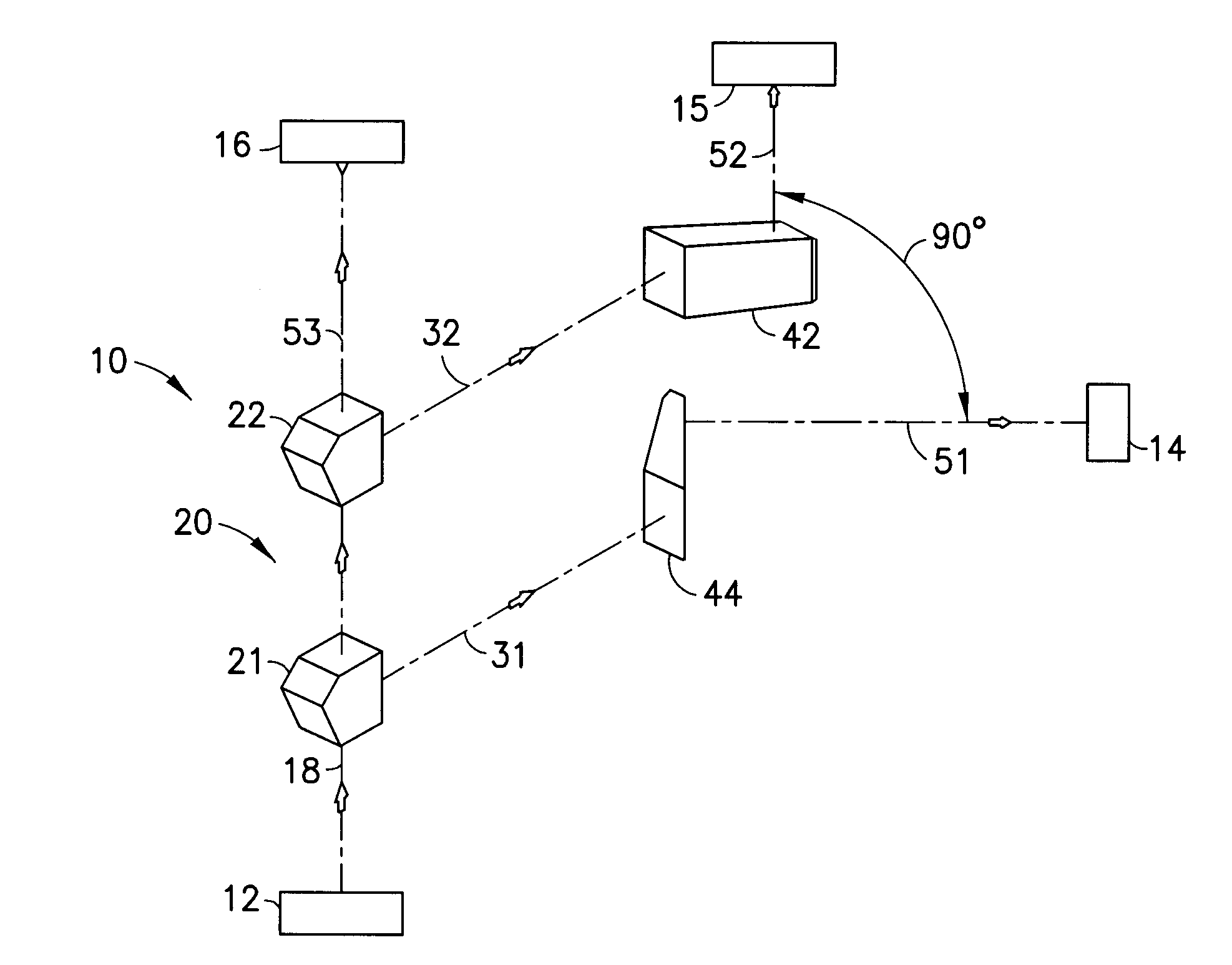
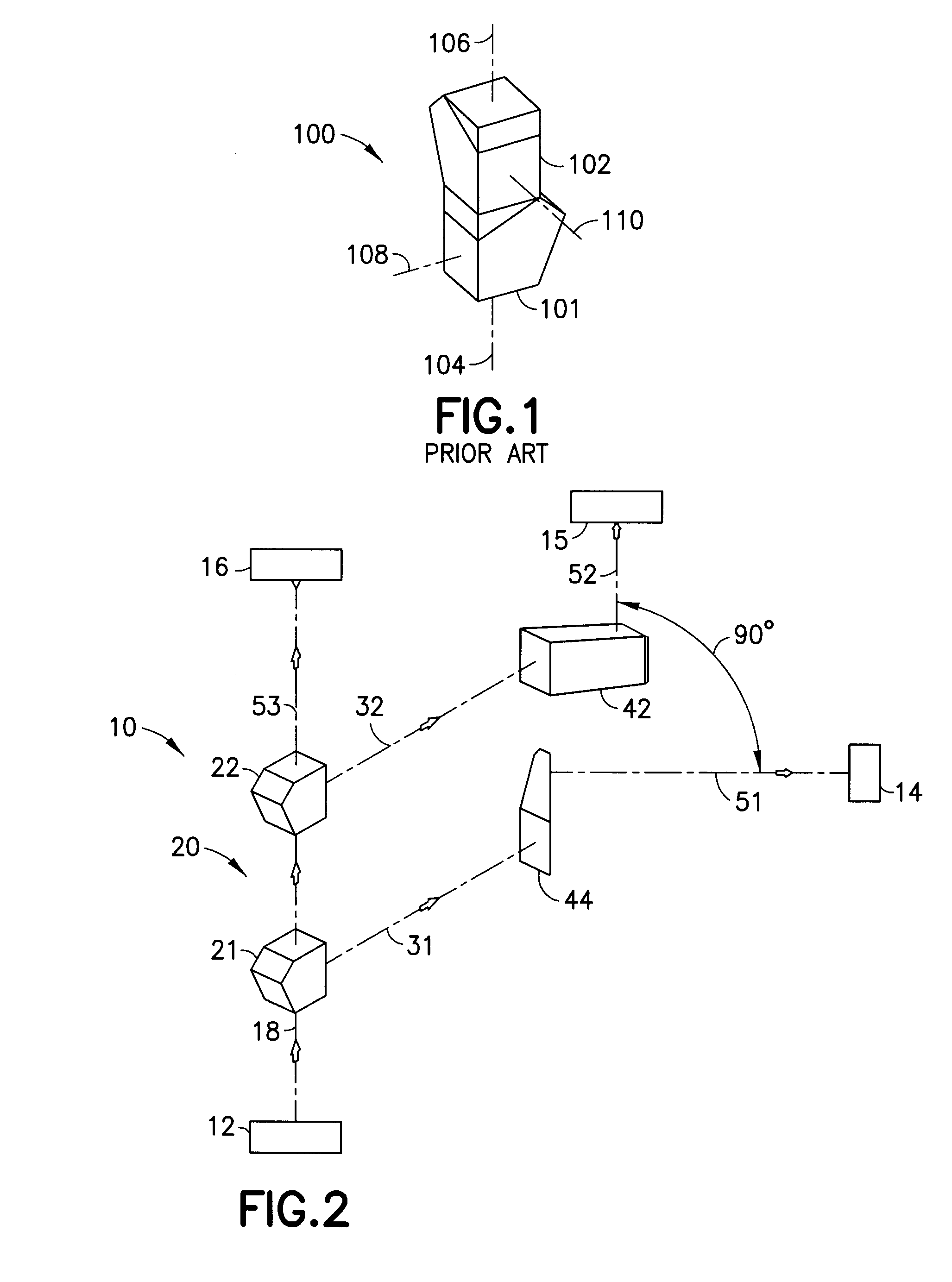
[0023]A laser alignment system in accordance with the invention is identified generally by the numeral 10 in FIGS. 2-5. The laser alignment system 10 includes a laser emitter 12 and first, second and third photosensitive target assemblies 14, 15 and 16. The laser emitter 12 and the photosensitive target assemblies 14-16 may be of known design. More particularly, the photosensitive target assemblies 14-16 may be configured to measure displacement relative to two mutually perpendicular axes and may be configured to measure alignment about mutually perpendicular axes (pitch and yaw). The laser emitter 12 is operative to produce an input beam 18.

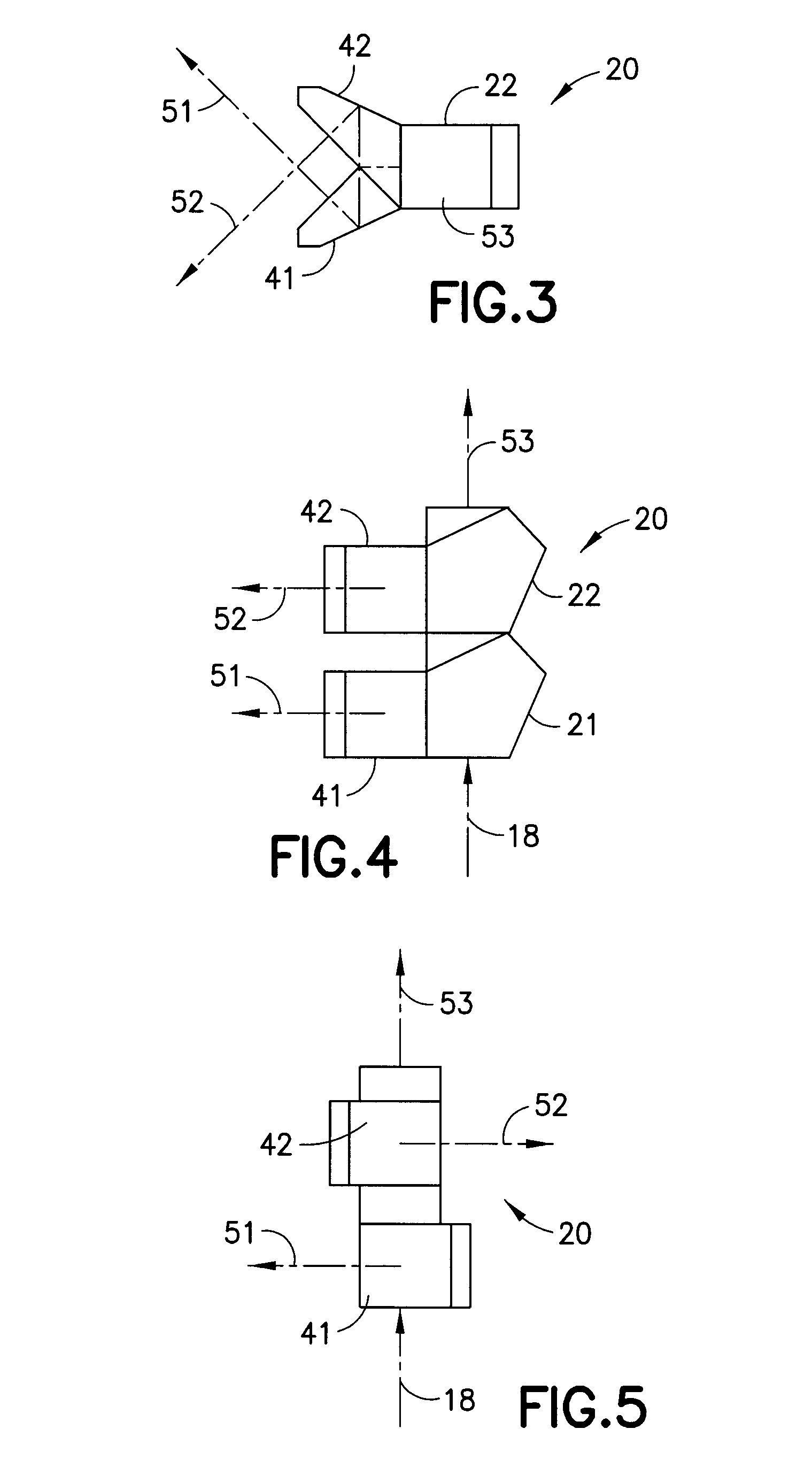
[0024]The laser alignment system 10 further includes an optical assembly 20. The optical assembly 20 is disposed to receive the input beam 18 from the laser emitter 12. More particularly, the optical assembly 20 includes first and second see-through or beam splitting 90° pentaprisms 21 and 22. The first and second 90° pentaprisms 21 and 22 are d...


PUM


Abstract

An optical assembly is provided for use with a laser alignment system that has a laser emitter and at least one photosensitive target. The optical assembly includes first and second 90° pentaprisms disposed for receiving an input beam produced by the laser emitter. The first and second 90° pentaprisms are oriented to produce first and second reflected beams that are parallel to one another. The optical assembly further includes first and second beam diverters disposed and oriented to receive the reflected beams from the first and second 90° pentaprisms and to produce first and second output beams that are mutually perpendicular. The first and second 90° pentaprisms may be see-through pentaprisms to produce a third output beam that is colinear with the input beam and perpendicular to the first and second output beams.

Description

CROSS-REFERENCE TO RELATED APPLICATION[0001]This application claims priority on U.S. Provisional Patent Appl. No. 61 / 716,008 filed on Oct. 19, 2012, the entire disclosure of which is incorporated herein by reference.BACKGROUND OF THE INVENTION[0002]1. Field of the Invention[0003]The invention relates to an optical apparatus or assembly that can be used with a laser emitter and a photosensitive target for aligning objects relative to one another.[0004]2. Description of the Related Art[0005]Laser emitters and photosensitive targets are used widely for aligning objects to one another. The prior art laser alignment system includes at least one laser emitter that projects a straight beam and at least one photosensitive target that can precisely determine the center of energy of the laser beam impinging thereon. The laser emitter and the photosensitive target can be mounted in a fixed relationship to objects that are to be aligned. The relative positions of the objects and the alignments ...

Claims


Application Information

Patent Timeline
IPC IPC(8): G02B27/12
CPCG02B27/126
Inventor HAMAR, MARTIN R.
Owner HAMAR LASER INSTR
Why Eureka
Try Eureka