Pressure Regulating Valve

Active Publication Date: 2014-04-24
HAMILTON SUNDSTRAND CORP
View PDF8 Cites 14 Cited by
  • Summary
  • Abstract
  • Description
  • Claims
  • Application Information

AI Technical Summary

Benefits of technology

The patent describes a valve structure that includes a sleeve and a piston. The sleeve is designed to fit around a central axis and has a cavity where the piston can slide against it. The piston has recessed areas that fit into the sleeve. When there is no pressure at the valve inlet, the piston is pushed closed by a spring. When there is pressure at the inlet, the piston moves to an open position to return fluid to the pump. The ratio between the inner diameter of the sleeve and the outer diameter of the piston is important for proper functioning of the valve. Overall, the valve structure described allows for precise control of fluid pressure and minimizes damage to the valve components.

Problems solved by technology

Existing pressure regulating valves may sometimes result in undesirable pressure setting shifts at different operating conditions.

Method used


Image

  • Pressure Regulating Valve
  • Pressure Regulating Valve
  • Pressure Regulating Valve

Examples


Embodiment Construction

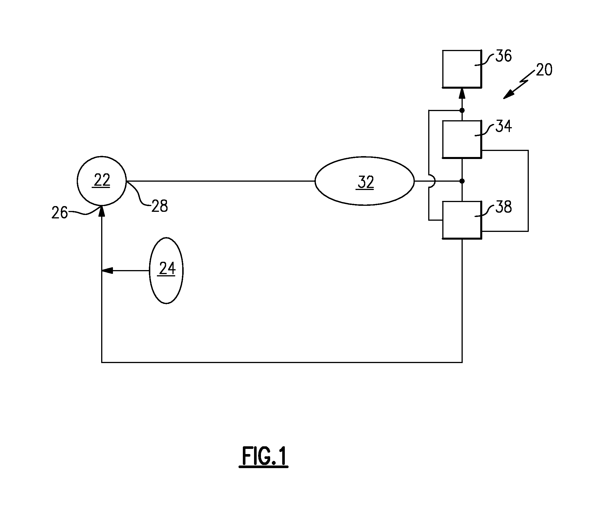
[0021]FIG. 1 shows a schematic view of an aircraft fuel supply system 20 having a fuel pump 22 drawing fuel from a fuel supply 24. The pump 22 has a pump inlet 26 in fluid communication with the fuel supply 24 and a pump outlet 28 in fluid communication with a metering valve 34 and a pressure regulating valve 38. Fuel passes through a filter 32 to remove contaminants. Fuel exiting the filter 32 is then directed to the metering valve 34 to supply fuel to an engine 36. The pressure regulating valve 38 receives pressure inputs from sense lines around the metering valve 34 to regulate the pressure across the metering valve 34. If the supply of fuel at the metering valve 34 is excessive for the current engine operating condition, the pressure regulating valve 38 returns the excess fuel to the pump inlet 26.

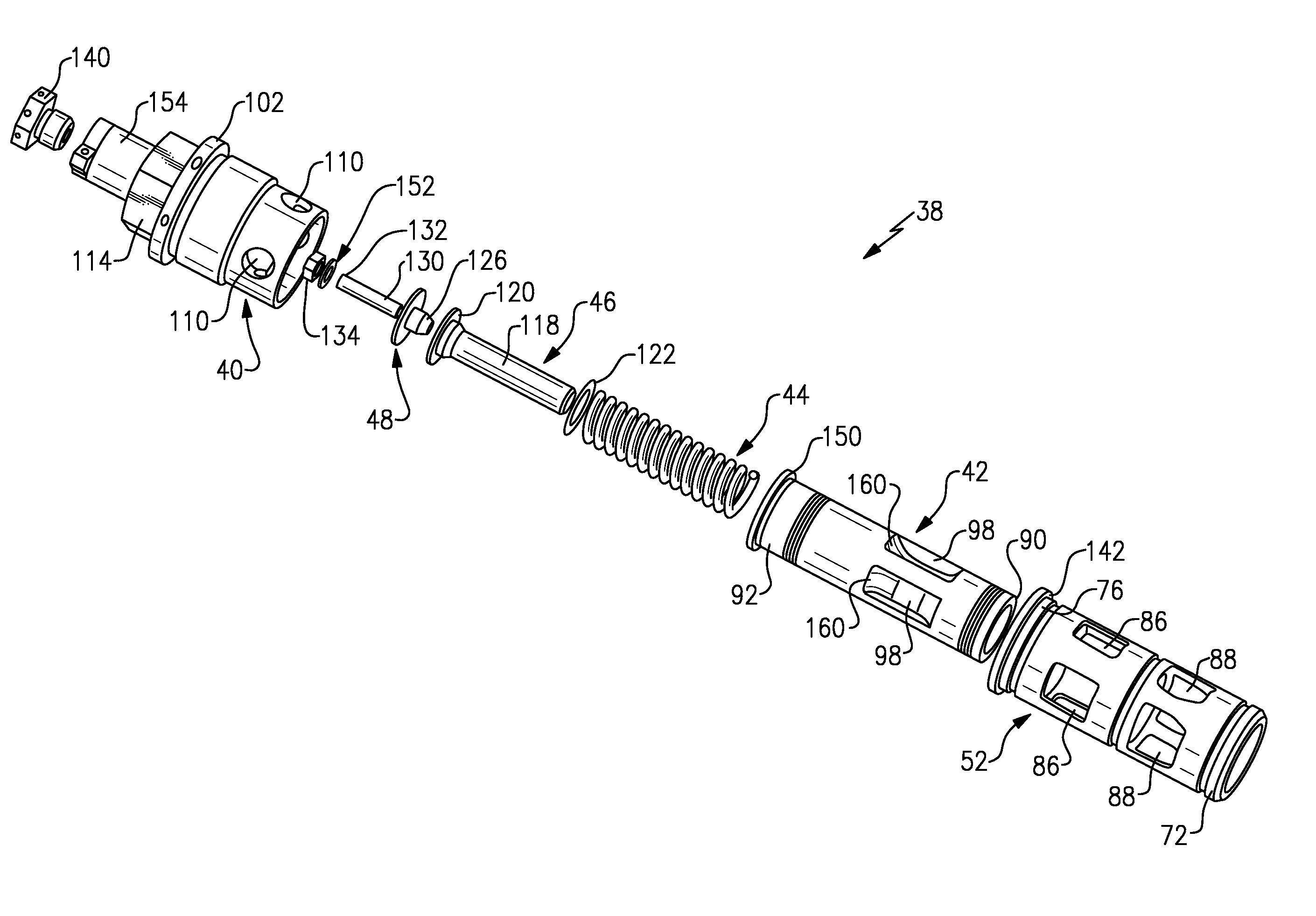
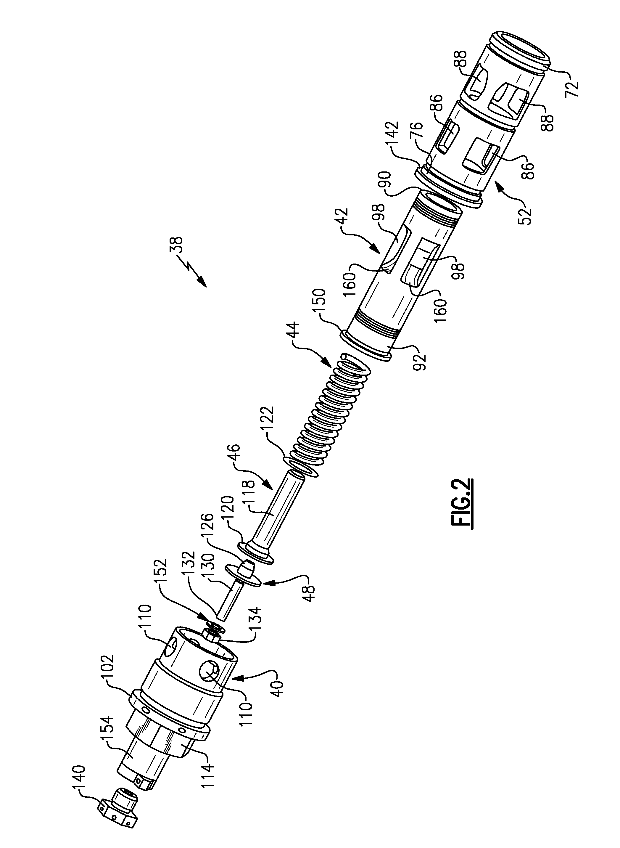
[0022]The pressure regulating valve 38 is shown in greater detail in FIGS. 2-4. The primary components of the pressure regulating valve 38 include a closure 40, piston 42, spring 44, s...


PUM


Abstract

In one featured embodiment, a sleeve for a valve includes a sleeve body surrounding a center axis and defined by an overall length extending from a first end to a second end. The sleeve body has a central bore extending from the first end to the second end. The central bore has a first surface portion comprising a piston contact surface that is defined by a first inner diameter, wherein the piston contact surface is configured to slide against a piston to be received within the central bore. In one example, a ratio of the overall length to the first inner diameter is between 3.51 and 3.63.

Description

BACKGROUND OF THE INVENTION[0001]This application relates to a pressure regulating valve which may be utilized in a fuel line for an aircraft engine.[0002]A gas turbine engine is typically used to power an aircraft. A fuel system provides fuel to various portions of the gas turbine engine. Fuel is primarily delivered into a combustor section of the gas turbine engine. Airflow through the gas turbine engine is compressed by one or more compressors, mixed and burned with fuel in the combustor, and then expanded over one or more turbines. The fuel is supplied to the gas turbine engine by a fuel pump from a fuel supply, and passes through a filter on the way to the engine. The fuel system also includes various valves, such as a pressure regulating valve, high pressure relief valve, filter bypass valve, etc., which cooperate with each other to supply fuel to the gas turbine engine in a controlled and accurate manner.[0003]The metering valve supplies a specified amount of fuel to the engi...

Claims


Application Information

Patent Timeline
IPC IPC(8): F16K51/00
CPCF16K51/00F16K11/07G05D16/10G05D16/028Y10T137/0441Y10T137/85978Y10T137/6851Y10T137/7793F16K31/1221F16K3/24
Inventor RICKIS, AARONPODGORSKI, DAVID J.
Owner HAMILTON SUNDSTRAND CORP
Why Eureka
Try Eureka