
Method of simulation of unsteady aerodynamic loads on an external aircraft structure

a technology of aerodynamic load and external aircraft, applied in the field of aerodynamics, can solve the problems of unsteady pressure fluctuation, difficult to correct it retrospectively, and prove very disadvantageous in terms of time and development cos

Inactive Publication Date: 2014-03-20
AIRBUS OPERATIONS (SAS)
View PDF19 Cites 9 Cited by
  • Summary
  • Abstract
  • Description
  • Claims
  • Application Information

AI Technical Summary

Benefits of technology

The present invention relates to the aerodynamic loads on an external aircraft structure caused by buffeting, and the simulation of unsteady aerodynamic loads on a wing surface. The technical effect of the invention is to provide a reliable and accurate method for simulating the buffeting phenomenon, which can affect the design phase of an aircraft and cause certification problems. The invention takes into account the independence of the movement of the structure and the instability of the flow on the wing surface, and uses a state model to model the coupling between the fluid and the structure. The invention also includes a method for measuring the unsteady aerodynamic loads on a wing surface using pressure sensors distributed across the wing surface during tests in a wind tunnel model.

Problems solved by technology

This phenomenon leads to a generation of unsteady pressure fluctuations in the separation area, and the origination of vortexes which themselves cause vibrations of the wing surface.
If it is not, it is difficult to correct it retrospectively, and this correction may prove very disadvantageous in terms of time and development cost.
However, in practice, the number of these sensors is greatly insufficient due to the spatial limitation on the model and the high cost of these sensors.
In addition, these Fourier / inverse Fourier transforms are of course undertaken in practice using FFTs / IFFTs which, due to the discretisation which they introduce, lead to a relatively inaccurate approximation of the unsteady pressure.

Method used


Image

  • Method of simulation of unsteady aerodynamic loads on an external aircraft structure
  • Method of simulation of unsteady aerodynamic loads on an external aircraft structure
  • Method of simulation of unsteady aerodynamic loads on an external aircraft structure

Examples


Embodiment Construction

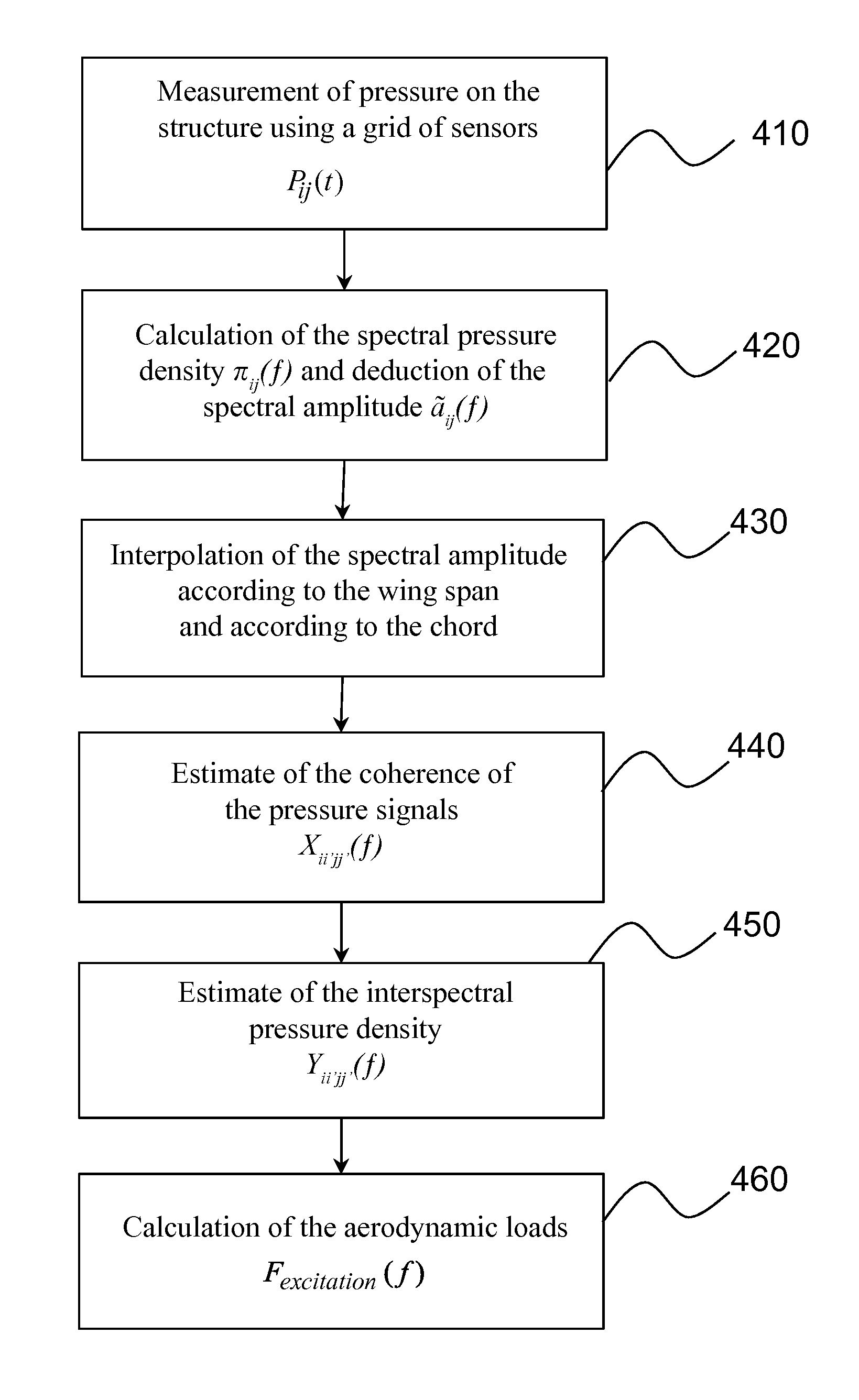
[0019]The present invention is defined by a method of computer simulation of the unsteady aerodynamic loads being exerted on an external structure of an aircraft, positioned in an airflow, where the said method includes:

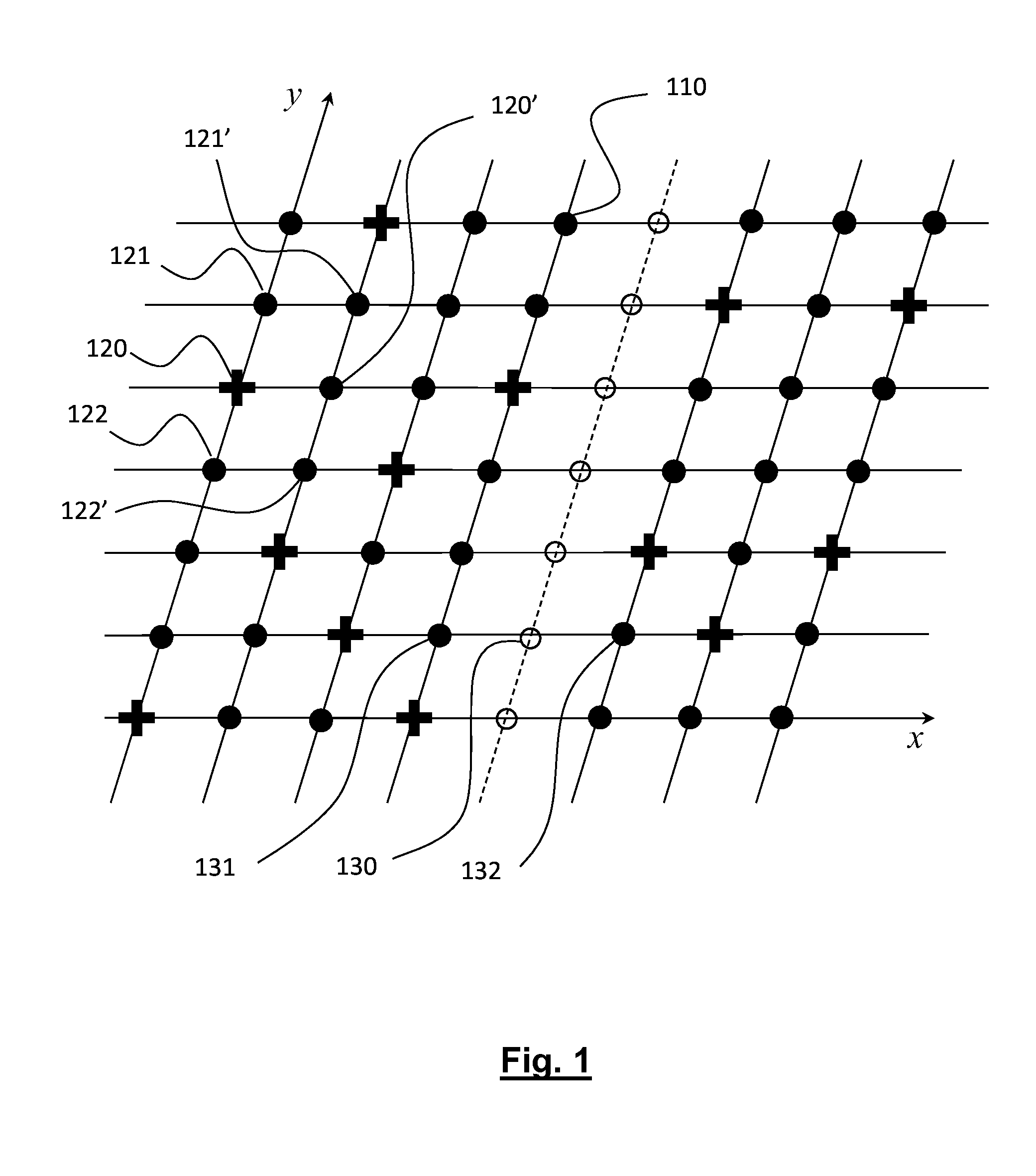
[0020](a) a step of measurement of pressure by multiple sensors located on the surface of the said structure, and positioned at the first points of a grid having a first direction in the flow direction, and a second direction, separate from the first, where the pressure signals of the said sensors are stored in a memory;

[0021](b) a step of calculation of the spectral density of the pressure signals at the said first points of the grid;

[0022](c) a step of extrapolation / interpolation of the spectral pressure density in order to obtain a spectral pressure density at second points of the grid not having sensors;

[0023](d) a step of estimation of the coherence of the pressure for multiple pairs of points of the grid, from a predetermined model of the coherence function;

[00...


PUM


Abstract

The invention relates to a method for simulating the unsteady aerodynamic loads being exerted on the external structure of an aircraft, notably in the context of a simulation of the buffeting of a wing surface in an airflow. The method includes a step of measurement of pressure (410) at different points of a grid, a step of calculation of the spectral density at these points (420) followed by extrapolation / interpolation operations to calculate the missing measurements (430), a step of estimation of the pressure coherence (440) for each pair of points of the grid, a step of estimation of the interspectral pressure density (450) for these same pairs of points, from the coherence thus estimated, and a step of calculation of the aerodynamic loads (460) by summing the real part of the interspectral density for the area of the wing surface having a separation of the boundary layer.

Description

TECHNICAL FIELD[0001]The present invention relates generally to the aerodynamics field, and more specifically that of the simulation of unsteady aerodynamic loads on an external aircraft structure.STATE OF THE PRIOR ART[0002]The phenomenon of buffeting of a wing surface is well known in the aerodynamics field. It is principally due to the separation of the boundary layer in certain areas on the wing surface. This phenomenon leads to a generation of unsteady pressure fluctuations in the separation area, and the origination of vortexes which themselves cause vibrations of the wing surface.[0003]Since the buffeting phenomenon reduces the aircraft's flight envelope it must be taken into account from the design phase. If it is not, it is difficult to correct it retrospectively, and this correction may prove very disadvantageous in terms of time and development cost. Simulation of the buffeting of a wing surface with a satisfactory degree of reliability is consequently essential to allow ...

Claims


Application Information

Patent Timeline
IPC IPC(8): G06F17/50
CPCG06F17/5009G01M9/065G06F30/20
Inventor CALDERON, RAULDAVID, CHRISTOPHE
Owner AIRBUS OPERATIONS (SAS)
Learn More