
Prosthetic Device for Handling a Ball

a technology for prosthetic devices and balls, applied in metal-working equipment, metal-working equipment, manufacturing tools, etc., can solve the problems of long felt and unresolved need for a prosthetic device for handling balls, and conventional prosthetic devices do not allow both retention of balls and release of balls

Active Publication Date: 2014-02-13
FILLAUER TRS INC
View PDF55 Cites 12 Cited by
  • Summary
  • Abstract
  • Description
  • Claims
  • Application Information

AI Technical Summary

Benefits of technology

The invention is a prosthetic device for handling a ball that is designed to be attached to a person's residual limb. It includes a connection point, a support arm, and a ball handling structure. The device can be easily adjusted to different types of balls and provides a comfortable fit. The method for using the device involves attaching it to the person's limb and engaging the ball handling structure to catch and release the ball. The technical effects of this invention include improved function and comfort for people with limb amputation and the ability to play a wide range of sports with a prosthetic device.

Problems solved by technology

However, until the instant invention, there remained a long felt and unresolved need for a prosthetic device for handling a ball.
This may be due to a variety of unresolved difficulties in the provision of a prosthetic structure for ball handling.
In the first instance, conventional prosthetic devices do not allow both retention of a ball unaided by another limb and also release of the ball in response to a substantially normal range of throwing movements of the remaining portion of a limb of an amputee.
Another difficulty involves provision of a prosthetic structure for handling a ball adjustable in the first instance to the lengths of the remaining limbs in a population of amputees and in the second instance to the range of throwing movements of the remaining portion of a limb of each particular amputee.
Another difficulty involves provision of a prosthetic structure for handling a ball which has an amount of flexure in response the mass and type of the ball being handled adjustable to aid in release of the ball from the prosthetic structure.
Another difficulty involves provision of a prosthetic device having a structure which allows the amputee to control the travel path of the ball toward a target based on a substantially normal range of throwing movements of the remaining portion of the limb of the amputee.
Another difficulty involves provision of a prosthetic device having a structure which allows the amputee to control the velocity of the ball in a travel path toward a target over a relative broad velocity range from a few miles per hour to over 40 miles per hour or even greater.

Method used


Image

  • Prosthetic Device for Handling a Ball
  • Prosthetic Device for Handling a Ball
  • Prosthetic Device for Handling a Ball

Examples


Embodiment Construction

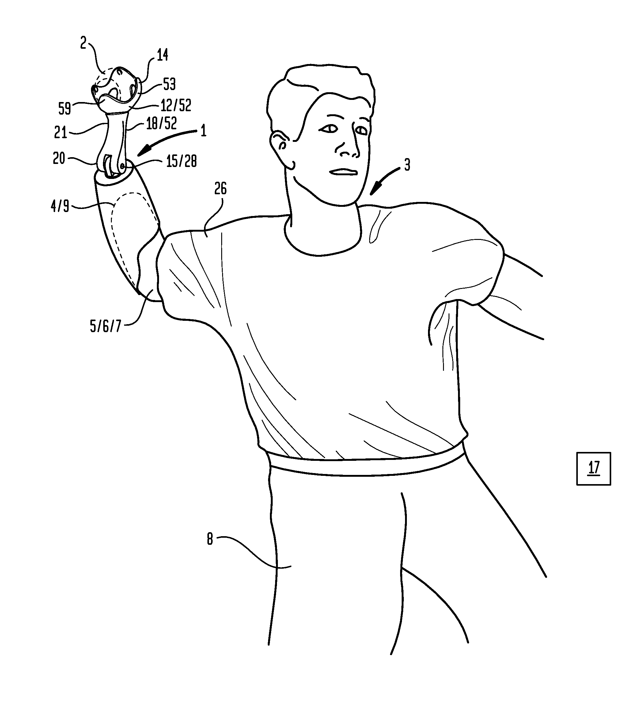
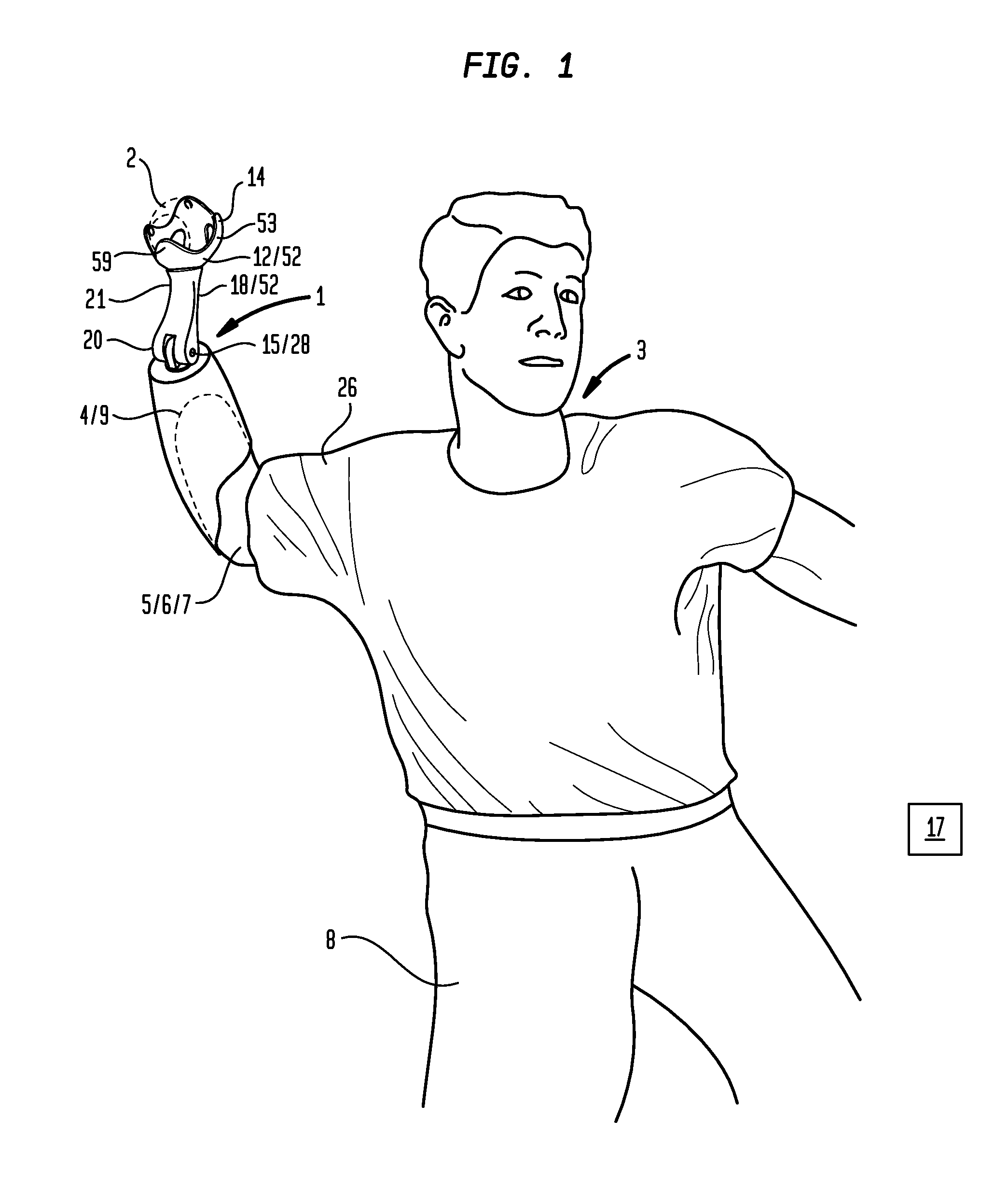
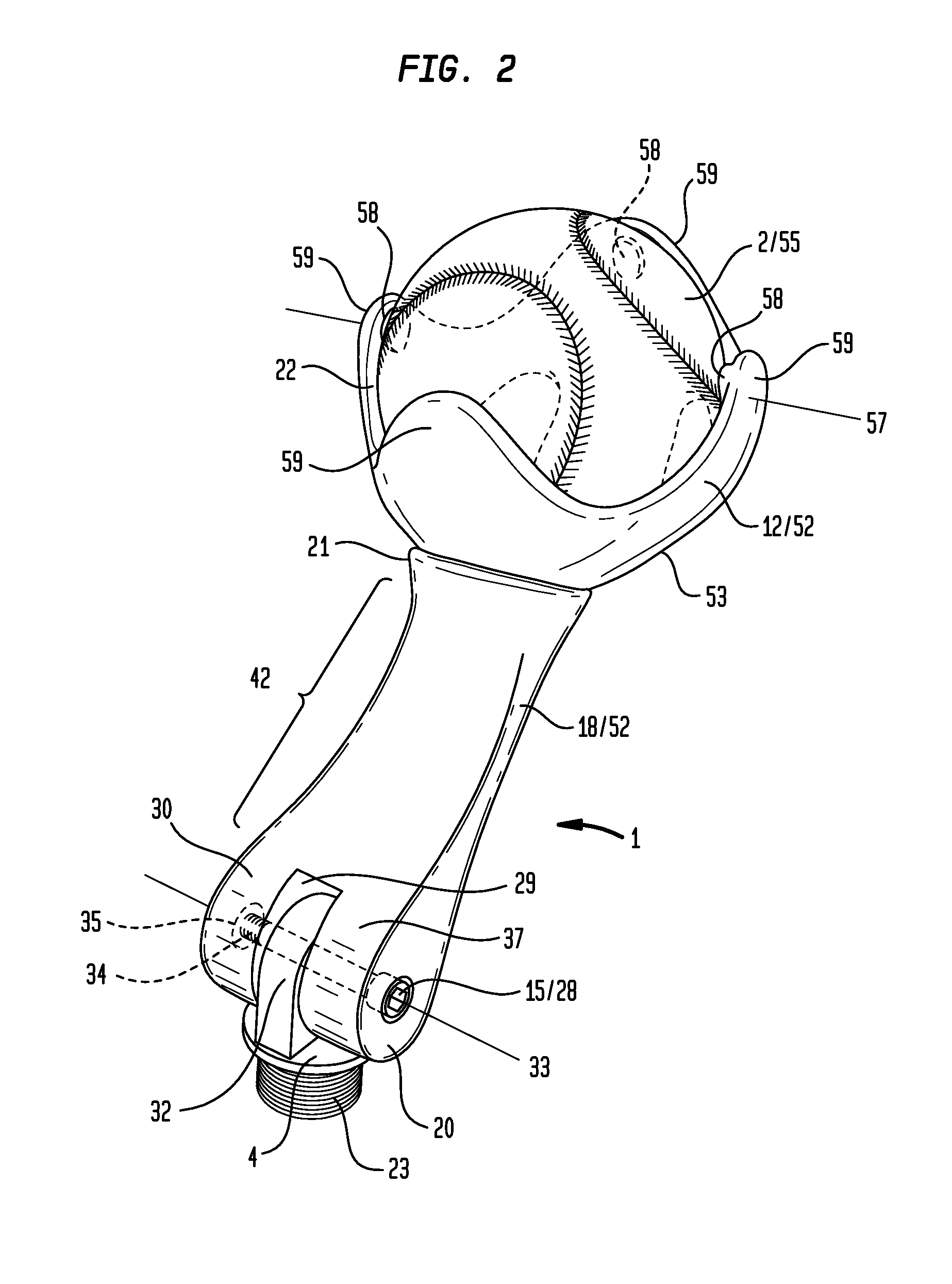
[0037]Now referring primarily to FIGS. 1 through 4, which illustrates a method of using a particular embodiment of the inventive prosthetic device (1) for handling a ball (2). For the purposes of this invention the term “ball” means an object having a body composed of one or more materials whether hollow or solid which can be, but is not limited to, a spherical form, with examples including: a baseball, as softball, tennis ball, golf ball, a pickle ball, a wiffle ball, or the like. An amputee (3) can obtain an embodiment of the prosthetic device (1) which includes an attachment portion (4) which can be coupled to a remaining portion (5) of a limb (6). For the purposes of this invention the term “amputee” means a person lacking a portion of a limb whether a result of amputation or congenital disorder. For the purposes of this invention, the term “limb” means an arm (7) or a leg (8). The term “coupled to” means any manner of attachment of the prosthetic device (1) to the amputee (3), ...


PUM

PropertyMeasurementUnit
Flexibilityaaaaaaaaaa
Heightaaaaaaaaaa
Responsivityaaaaaaaaaa

Abstract

A prosthetic device which couples to the remaining portion of a limb of an amputee which provides a ball handling structure including a ball handling surface which defines an opening through which a ball passes into and out of a ball receiving cavity allowing the ball to be handled by the amputee.

Description

I. FIELD OF THE INVENTION[0001]A prosthetic device which couples to the remaining portion of a limb of an amputee which provides a ball handling structure including a ball handling surface which defines an opening through which a ball passes into and out of a ball receiving cavity allowing the ball to be handled by the amputee.II. BACKGROUND OF THE INVENTION[0002]There are a numerous and wide range of prosthetic devices which can be coupled to the remaining portion of the limb of an amputee. However, until the instant invention, there remained a long felt and unresolved need for a prosthetic device for handling a ball. This may be due to a variety of unresolved difficulties in the provision of a prosthetic structure for ball handling.[0003]In the first instance, conventional prosthetic devices do not allow both retention of a ball unaided by another limb and also release of the ball in response to a substantially normal range of throwing movements of the remaining portion of a limb ...

Claims


Application Information

Patent Timeline
IPC IPC(8): B23P11/00
CPCA61F2/588Y10T29/49826Y10T29/49947Y10T29/49963Y10T29/49966
Inventor RADOCY, ROBERT
Owner FILLAUER TRS INC
Learn More