Airfoil

Active Publication Date: 2014-01-16
GENERAL ELECTRIC CO
View PDF1 Cites 8 Cited by
  • Summary
  • Abstract
  • Description
  • Claims
  • Application Information

AI Technical Summary

Benefits of technology

This patent describes an airfoil with specific features. The airfoil has a leading edge, a trailing edge, a pressure surface, and a suction surface. The suction surface has a first concave section and a second concave section, and the first concave segment increases in curvature. The pressure surface has a first convex section and a second convex section, and the first convex segment increases in curvature. The technical effects of this design include improved aerodynamic performance and stability.

Problems solved by technology

At higher differential pressures, the compressed working fluid may reach supersonic velocities as it passes through the turbine, creating considerable shock waves and reflected shock waves between adjacent rotating blades and corresponding shock losses at the trailing edge of the rotating blades.
The resultant shock waves and corresponding shock losses may limit the maximum power output of the turbine as the maximum tangential force is reached.
If the pressure ratio increases beyond the limit load, a drastic increase in loss occurs.
At a sufficiently low pressure ratio, the shock reflection becomes normal, thus leading to high loss and corresponding reduction in turbine efficiency.
As a result, the maximum power output of the turbine may be limited by colder ambient temperatures.

Method used


Image

  • Airfoil
  • Airfoil
  • Airfoil

Examples


first embodiment

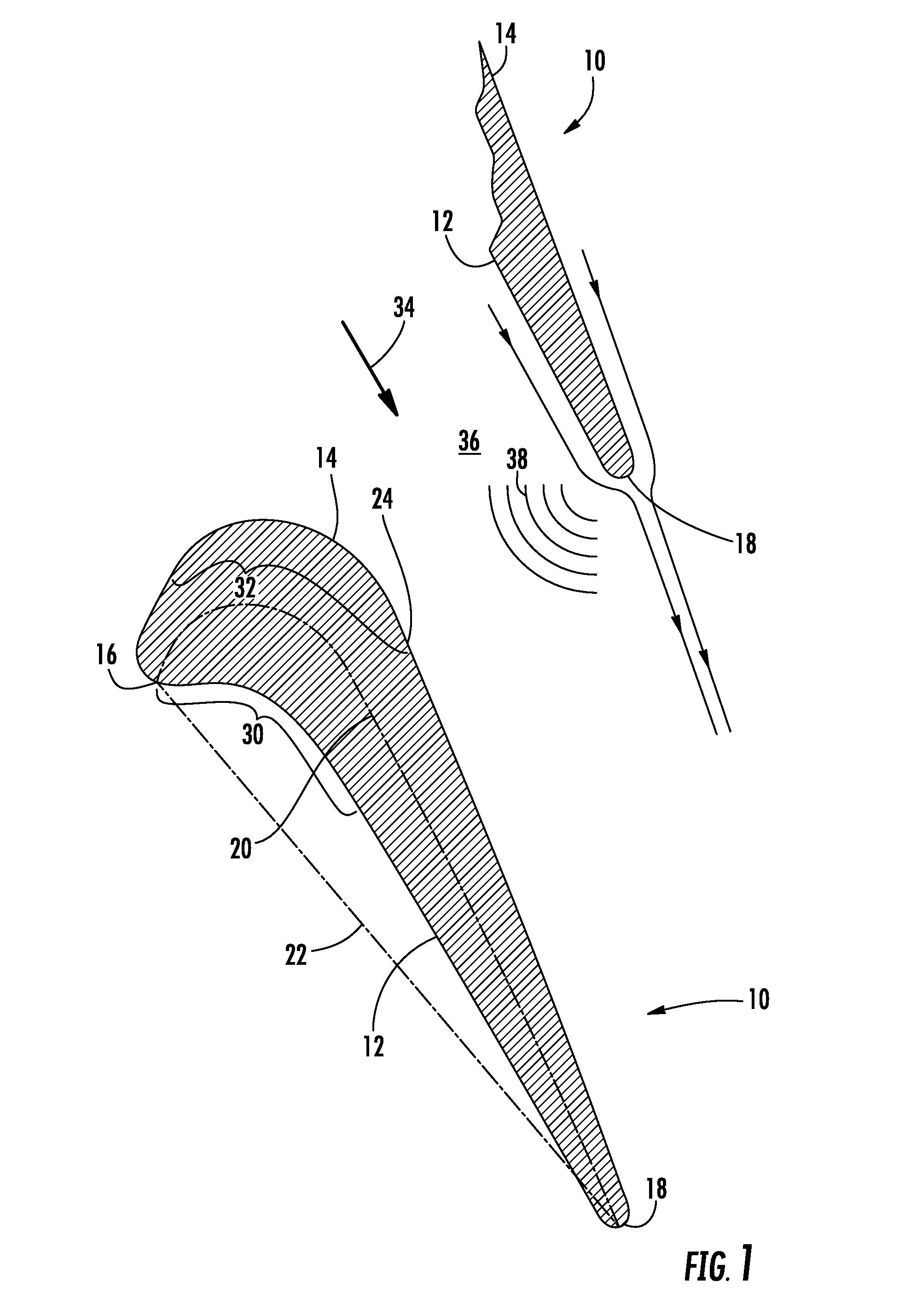
[0021]FIG. 2 provides a radial cross-section view an airfoil 40 according to the present invention, with the outline of the exemplary airfoil 10 shown in dashed lines for comparison. As shown in FIG. 2, the airfoil 40 includes a leading edge 42 and a trailing edge 44 downstream from the leading edge 42. A pressure surface 46 is opposed to a suction surface 48 between the leading and trailing edges 42, 44. FIG. 3 provides an exemplary graph of the curvature of the airfoil 40 shown in FIG. 2, with the curvature of the airfoil 10 shown in FIG. 1 shown in dashed lines. The horizontal axis in FIG. 3 represents the chord length between the leading edge 42 and the trailing edge 44, and the vertical axis represents the amount of curvature in the pressure and suction surfaces 46, 48. By convention, the area above the horizontal axis represents convex curvature, and the area below the horizontal axis represents concave curvature.

[0022]As shown in FIG. 2, the pressure surface 46 includes a fir...

second embodiment

[0024]FIG. 4 provides a radial cross-section view the airfoil 40 according to the present invention, and FIG. 5 provides an exemplary graph of the curvature of the airfoil 40 shown in FIG. 3. The airfoil 40 generally includes the same contours for the pressure and suction surfaces 46, 48 as previously described with respect to FIGS. 2 and 3. In addition, the suction surface 48 includes an intermediate section 70 between the first convex section 62 and the second convex section 64. The intermediate section 70 may commence near a throat 72 on the suction surface 48 and extend downstream toward the second convex section 64 with a curvature of zero.

[0025]One of ordinary skill in the art will readily appreciate from the teachings herein that the magnitude and / or length of the particular concave, convex, and intermediate sections will vary according to particular embodiments and placement in the turbine, and the present invention is not limited to any specific magnitudes or lengths unless...


PUM


Abstract

An airfoil includes a leading edge, a trailing edge downstream from the leading edge, a pressure surface between the leading and trailing edges, and a suction surface between the leading and trailing edges and opposite the pressure surface. A first convex section on the suction surface decreases in curvature downstream from the leading edge, and a throat on the suction surface is downstream from the first convex section. A second convex section is on the suction surface downstream from the throat, and a first convex segment of the second convex section increases in curvature.

Description

FEDERAL RESEARCH STATEMENT[0001]This invention was made with Government support under Contract No. DE-FC26-05NT42643, awarded by the Department of Energy. The Government has certain rights in the invention.FIELD OF THE INVENTION[0002]The present disclosure generally involves an airfoil and a method for reducing shock loss in a turbine by enhancing the airfoil curvature aft of the throat.BACKGROUND OF THE INVENTION[0003]Turbines are widely used in a variety of aviation, industrial, and power generation applications to perform work. Each turbine generally includes alternating stages of peripherally mounted stator vanes and axially mounted rotating blades. The stator vanes may be attached to a stationary component such as a casing that surrounds the turbine, while the rotating blades may be attached to a rotor located along an axial centerline of the turbine. The stator vanes and rotating blades each have an airfoil shape, with a concave pressure side, a convex suction side, and leadin...

Claims


Application Information

Patent Timeline
IPC IPC(8): F01D5/14
CPCF01D5/141F05D2240/304F05D2250/711F05D2250/712
Inventor RISTAU, NEILSIDEN, GUNNAR LEIF
Owner GENERAL ELECTRIC CO
Why Eureka
Try Eureka