Apparatus and methods for reducing foaming during saliva collection

a saliva collection and apparatus technology, applied in the field of medical devices and methods, can solve the problems of simple barrier itself being fouled, risking saliva reaching the vacuum pump or other vacuum source, and the operation of the vacuum system, so as to reduce or eliminate the formation of bubbles and foam

Active Publication Date: 2014-01-16
SOMNICS INC
View PDF7 Cites 8 Cited by
  • Summary
  • Abstract
  • Description
  • Claims
  • Application Information

AI Technical Summary

Benefits of technology

The present invention provides an improved apparatus and methods for collecting saliva from aspirated air streams entrained with saliva, typically originating from a patient's oral cavity. The invention addresses the problem of excessive bubbles and foam in the collection reservoir, which can result in loss of saliva through an outlet port on the reservoir. The invention includes a reservoir with a bubble barrier and a membrane to prevent bubbles and foam from reaching the vacuum pump or other vacuum source. The membrane allows air to pass with minimal restriction while preventing liquid saliva from passing through. The invention also includes inlet and outlet valves for easy removal of the reservoir from the system. The technical effects of the invention include improved collection of saliva with reduced bubbles and foam, minimized risk of saliva spillage, and efficient removal of the reservoir from the system.

Problems solved by technology

While a simple collection reservoir may be placed in a vacuum line from the oral cavity before the pump, as described in U.S. Patent Publication No. 2012 / 0132216, where the majority of saliva will drop to the bottom of the collection reservoir, excessive bubbles and foaming can result in loss of saliva through an outlet port on the reservoir, thus risking saliva reaching the vacuum pump or other vacuum source.
While the passage of saliva bubbles and foam through the outlet port might be overcome by a simple membrane or other barrier placed over the outlet port, it has been found by the inventors herein that such a simple barrier can itself become fouled over time which can interfere with operation of the vacuum system.
Thus, even if saliva is inhibited from leaking from the reservoir, operation of the vacuum system may still be impaired.
The bubble barrier is spaced apart from the outlet and disrupts bubbles and foam present in the air stream before such bubbles and foam can reach the outlet or membrane.

Method used


Image

  • Apparatus and methods for reducing foaming during saliva collection
  • Apparatus and methods for reducing foaming during saliva collection
  • Apparatus and methods for reducing foaming during saliva collection

Examples


Embodiment Construction

[0030]The novel features of the invention are set forth with particularity in the appended claims. A better understanding of the features and advantages of the present invention will be obtained by reference to the following detailed description that sets forth illustrative embodiments, in which the principles of the invention are utilized, and the accompanying drawings of which:

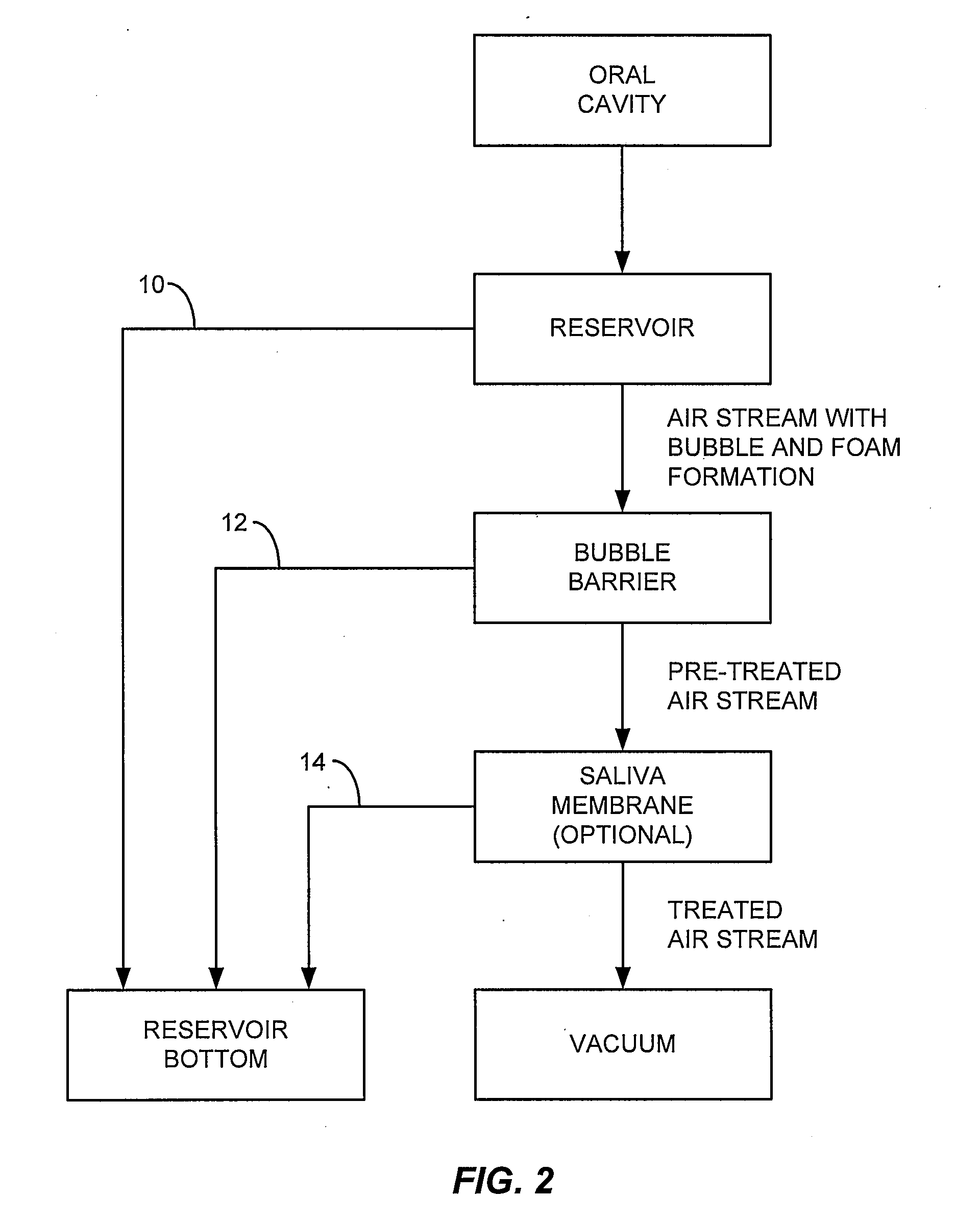
[0031]The saliva collectors and reservoirs of the present invention may be used in a variety of systems, typically systems where a vacuum line is being used to withdraw an air stream from a patient's oral cavity. Exemplary of such systems is system 489 illustrated in FIG. 1 where the reservoirs of the present invention might be used in place of conventional saliva reservoir 494.

[0032]Referring to FIG. 2, the apparatus and methods of the present invention provide for drawing an air stream from an oral cavity using a vacuum source, such as a pump. The air stream first passes into a reservoir where a first volu...


PUM


Abstract

A saliva collector comprises a reservoir, a bubble barrier, and a membrane, where the bubble barrier and membrane are arranged in tandem on a flow path from an inlet to an outlet on the reservoir. Air aspirated from a patient's oral cavity enters the reservoir through the inlet, passes through the bubble barrier to remove foam and bubbles, passes through the membrane to remove entrained liquid saliva, and passes out through the outlet.

Description

BACKGROUND OF THE INVENTION[0001]1. Field of the Invention[0002]The present invention relates generally to medical devices and methods. In particular, the present invention relates to a reservoir and methods for its use for the collection of saliva with a reduction in bubbling and foaming.[0003]A vacuum may be applied to an appliance or device held in a patient's oral cavity for a variety of purposes. For example, an appliance for treating obstructive sleep apnea (OSA) may utilize a device held in a patient's mouth where a vacuum is constantly drawn on the device in order to reposition portions of the patient's oral anatomy to reduce the likelihood of OSA. The device may be used for or in conjunction with drawing a patient's tongue and / or lower mandible forward in order to reduce OSA. Of particular interest to the present invention, the vacuum may be drawn in order to help draw the soft palate and / or rear portion of a patient's tongue away from the pharynx in order to maintain a cle...

Claims


Application Information

Patent Timeline
IPC IPC(8): A61M16/00
CPCA61M16/00A61F5/566A61C17/065A61M1/60A61M16/049A61M16/0463
Inventor VITALE, NICHOLAS R.MEJIA, KENNETHHOLZBAUR, MICHAEL R.CROWE, JOHN EDWARDSPODMORE, JONATHAN L.
Owner SOMNICS INC
Why Eureka
Try Eureka