Load Transferring Systems and Methods for Transferring Load in a Joint

a load transfer and joint technology, applied in the field of body anatomy structure attachment, can solve the problems of imbalance of forces and pain in the affected joint, requiring substantial recovery periods, and no current available chondroprotective therapies

Active Publication Date: 2013-12-05
MOXIMED INC
View PDF2 Cites 21 Cited by
  • Summary
  • Abstract
  • Description
  • Claims
  • Application Information

AI Technical Summary

Problems solved by technology

Such joint replacement procedures are a last resort treatment as they are highly invasive and require substantial periods of recovery.
Because of this, none of these currently available therapies are chondro-protective.
A misalignment due to injury or disease in a joint related to the direction of load can result in an imbalance of forces and pain in the affected joint.
However, HTO does not address ligamentous instability—only mechanical alignment.
Good early results associated with HTO often deteriorate over time.
If the load falls below the nominal range for extended periods of time, bone and cartilage can become softer and weaker (atrophy).
Osteoarthritis or breakdown of cartilage due to wear and tear can also result from overloading.
When cartilage breaks down, the bones rub together and cause further damage and pain.
Finally, if the load rises too high, then abrupt failure of bone, cartilage and other tissues can result.
The treatment of osteoarthritis and other bone and cartilage conditions is severely hampered when a surgeon is not able to control and prescribe the levels of joint load.
However, lack of patient compliance and the inability of the devices to facilitate and support the natural motion and function of the diseased joint have been problems with these external braces.

Method used


Image

  • Load Transferring Systems and Methods for Transferring Load in a Joint
  • Load Transferring Systems and Methods for Transferring Load in a Joint
  • Load Transferring Systems and Methods for Transferring Load in a Joint

Examples


Embodiment Construction

[0042]The present disclosure now will be described more fully hereinafter with reference to the accompanying drawings. The disclosure may be embodied in many different forms and should not be construed as limited to the embodiments set forth herein; rather, these embodiments are provided so that this disclosure will satisfy applicable legal requirements. Like numbers refer to like segments throughout. As used in this specification and the claims, the singular forms “a,”“an,” and “the” include plural references unless the context clearly dictates otherwise.

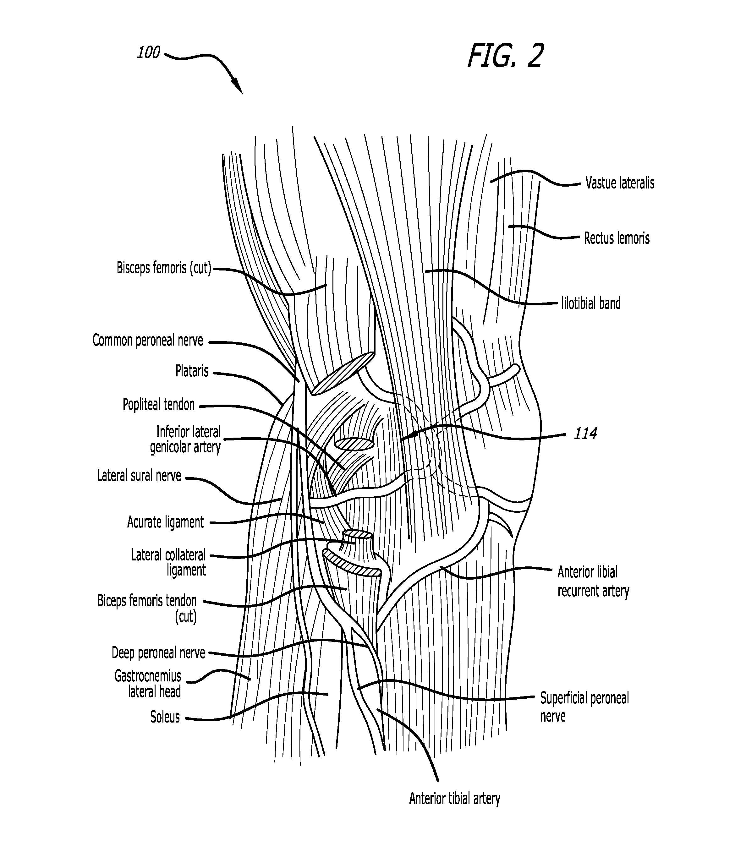
[0043]As described herein, embodiments of the disclosure relate to load transferring systems for a joint, and related methods. In one exemplary embodiment, the load transferring systems and methods are configured to address osteoarthritis of the lateral compartment of a knee joint. However, it should be understood that the systems and method described herein may be employed with other joints and maladies associated therewith.

[0044]...


PUM


Abstract

Load transferring systems and related methods for transferring load in a joint are provided. The load transferring system may include two bases configured to couple to bones defining a joint and a spring configured to couple to the bases. The spring may be configured to exert a tensile force between the bases during flexion of the joint. The load transferring system may be employed to treat symptoms associated with osteoarthritis of the lateral compartment of the knee joint. Thus, the bases may respectively couple to the femur and tibia. The spring may exert tensile force therebetween during flexion of the knee joint so as to unload the lateral compartment of the knee joint by transferring load from the lateral compartment of the knee joint to the medial compartment of the knee joint.

Description

CROSS REFERENCES TO RELATED APPLICATIONS[0001]This application claims the benefit of U.S. Application Ser. No. 61 / 646,738, filed May 14, 2012, the entire disclosure of which is expressly incorporated herein.FIELD OF THE DISCLOSURE[0002]Various embodiments disclosed herein are directed to structures for attachment to body anatomy, and more particularly, towards load transferring systems for attachment to joints and related methods.BACKGROUND[0003]Joint replacement is one of the most common and successful operations in modern orthopaedic surgery. It consists of replacing painful, arthritic, worn or diseased parts of a joint with artificial surfaces shaped in such a way as to allow joint movement. Osteoarthritis is a common diagnosis leading to joint replacement. Such joint replacement procedures are a last resort treatment as they are highly invasive and require substantial periods of recovery. Total joint replacement, also known as total joint arthroplasty, is a procedure in which al...

Claims


Application Information

Patent Timeline
Patent Type & Authority Applications(United States)
IPC IPC(8): A61F2/38
CPCA61F2/38A61B17/56A61B2017/567
Inventor CLIFFORD, ANTON G.JONES, ANDREW H.AZIZ, IMRAANSLONE, CLINTON N.KING, THOMASSTRASSER, MICHAELREGAN, DES
Owner MOXIMED INC
Why Eureka
Try Eureka