
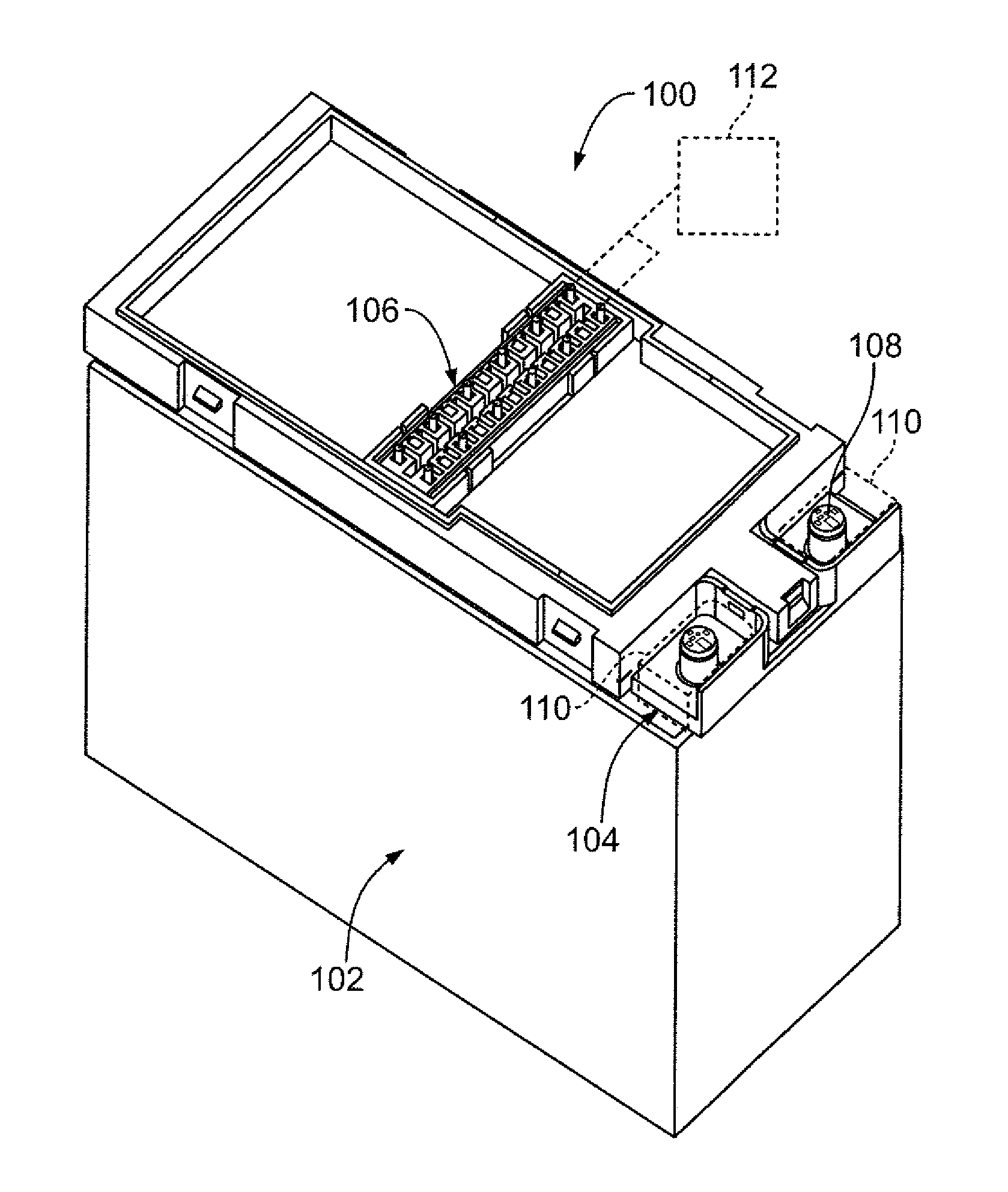
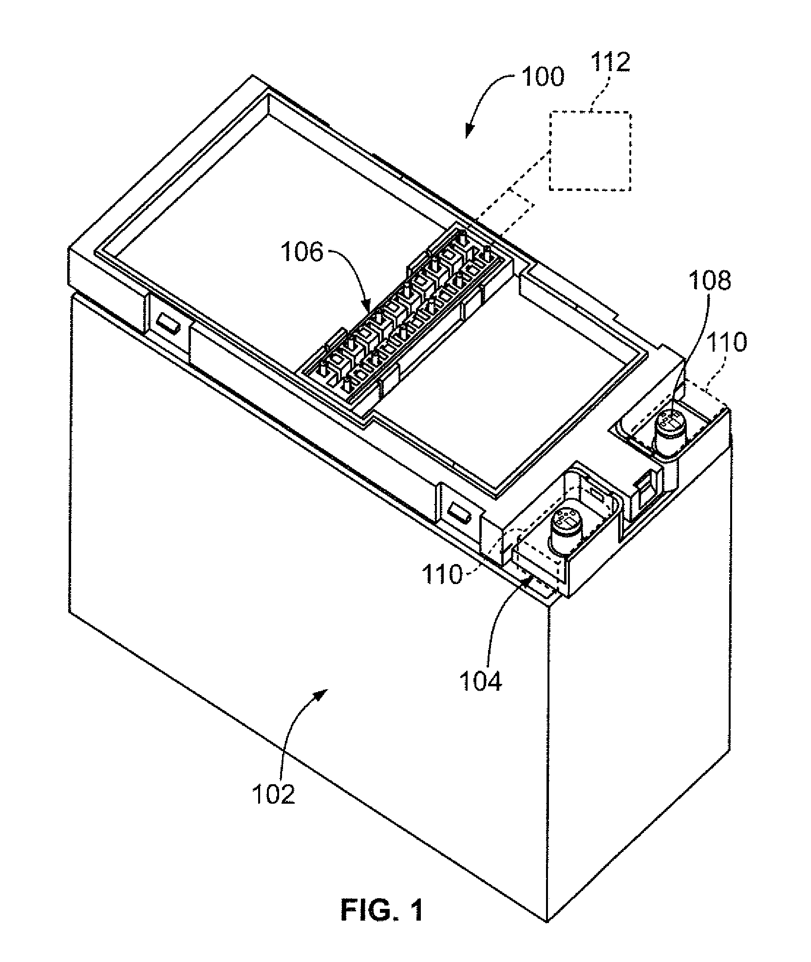
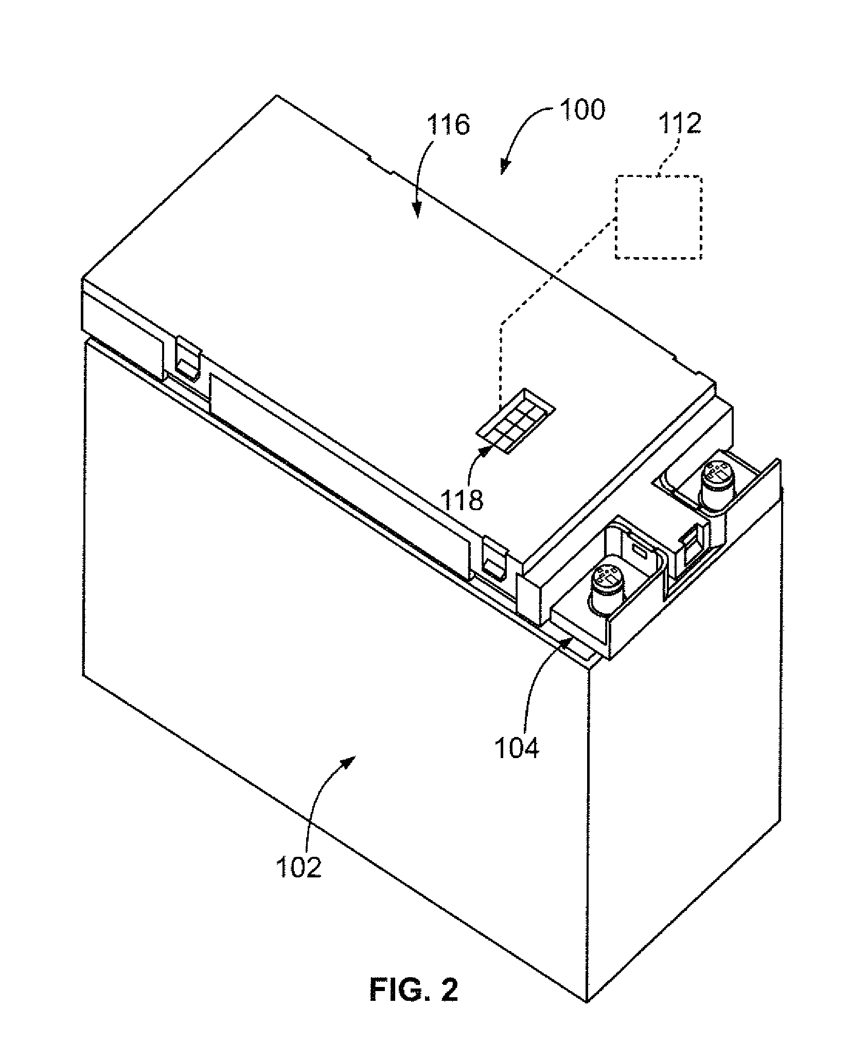
Battery connector system

a battery connector and connector technology, applied in the direction of batteries, coupling device connections, cell components, etc., can solve the problems of complex arrangement of parts and between the busbars

Inactive Publication Date: 2013-10-31
TE CONNECTIVITY CORP
View PDF50 Cites 84 Cited by
  • Summary
  • Abstract
  • Description
  • Claims
  • Application Information

AI Technical Summary

Benefits of technology

The patent describes a battery connector system for a battery module made up of multiple battery cells. The system includes a tray assembly with a tray and busbars that are connected to the tray. The busbars have fuse terminals and fuses connected between them and the electrical connector. The technical effect of this system is that it provides a reliable and flexible way to connect multiple battery cells in a battery module, ensuring proper functionality and performance.

Problems solved by technology

Problems exist with connections between the busbars and other components of the battery management system.
For example, typically the systems have many parts and have a complex arrangement of the parts.

Method used


Image

  • Battery connector system
  • Battery connector system
  • Battery connector system

Examples


Embodiment Construction

[0036]Current battery modules contain a series of battery cells. Typically the cells are aligned in parallel. Each cell has a positive and negative terminal. Typically busbars are welded to the cell terminals to sense the voltage so that the control system can sense and control the battery cell. The controller may be directly attached or connected to the battery module with a printed circuit board connector or, the controller may be remotely located and connected to the battery module with a wire harness connector. A sensing circuit is established between the battery cell busbars and the controller. Each sensing circuit is protected by a fuse. Embodiments described herein provide a fused battery connector system with a serviceable or resettable fuse.

[0037]Embodiments described herein are designed to function in a centralized battery management system or a decentralized battery management system. For example, embodiments of the fused battery connector system can be used with a direct...


PUM

PropertyMeasurementUnit
temperatureaaaaaaaaaa
voltageaaaaaaaaaa
electricallyaaaaaaaaaa

Abstract

A battery connector system includes a tray assembly configured to be mounted to a battery module made from a plurality of battery cells. The tray assembly has a tray and a plurality of busbars held by the tray. The tray has a tray connector defining a mating interface being configured to mate with an electrical connector. The electrical connector may be either a wire harness connector or a circuit board connector. The busbars are coupled to the tray and have plates being configured to be electrically connected to corresponding cell tabs of the battery cells. The busbars have fuse terminals positioned in the tray connector. A plurality of fuses are coupled to the fuse terminals. The fuses may be serviceable fuses or resettable fuses. The fuses are connected between the plates of the busbars and the electrical connector.

Description

CROSS REFERENCE TO RELATED APPLICATIONS[0001]This application claims the benefit of U.S. Provisional Application No. 61 / 639,552 filed Dec. 14, 2011, the subject matter of which is herein incorporated by reference in its entirety.BACKGROUND OF THE INVENTION[0002]The subject matter herein relates generally to battery connector systems.[0003]Batteries, such as those for electric vehicles or hybrid vehicles, typically include a plurality of cells grouped together as battery modules. The modules are connected together to form battery packs. Each of the cells include positive and negative tabs that are electrically connected together. Typically, busbars are welded to the cell tabs for sensing the voltage of the cells. A central or de-central battery management system is connected to the busbars for sensing and managing the battery cells.[0004]Problems exist with connections between the busbars and other components of the battery management system. For example, typically the systems have m...

Claims


Application Information

Patent Timeline
Patent Type & Authority Applications(United States)
IPC IPC(8): H01R13/73H01M50/209H01M50/211H01M50/298H01M50/503H01M50/507H01M50/519H01M50/528H01M50/583
CPCH01R13/73H01M10/425H01M10/486H01R9/226H01M2220/20H01M2200/103H01R13/684H01M50/528H01M50/581H01M50/211H01M50/503H01M50/507H01M50/298H01M50/209H01M50/519H01M50/583Y02E60/10H01M50/50H01M50/531H01M50/543
Inventor ZHAO, WEIPING
Owner TE CONNECTIVITY CORP
Learn More